This helps you quickly interpret patents by identifying the three key elements:
Problems solved by technology
Method used
Benefits of technology
Problems solved by technology
[0002] In the field of construction, it is often necessary to tap some workpieces in order to install the workpieces. Now when tapping the workpieces, if the workpieces are small, the workpieces are generally tapped manually by turning the taps, because tapping requires a large This will greatly reduce the tapping efficiency. If the workpiece is large, it needs to be transported to a larger tapping equipment for tapping, which is very inconvenient.
Method used
Image
Click on the blue label to locate the original text in one second.
Reading with bidirectional positioning of images and text.
Examples
Embodiment 1
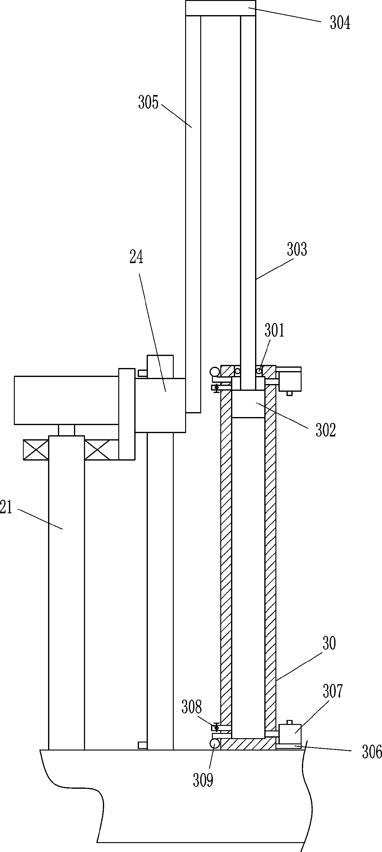
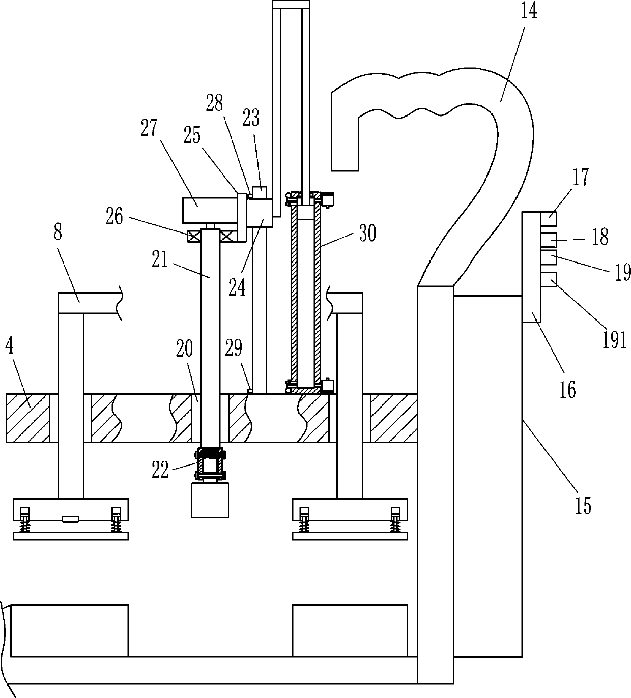
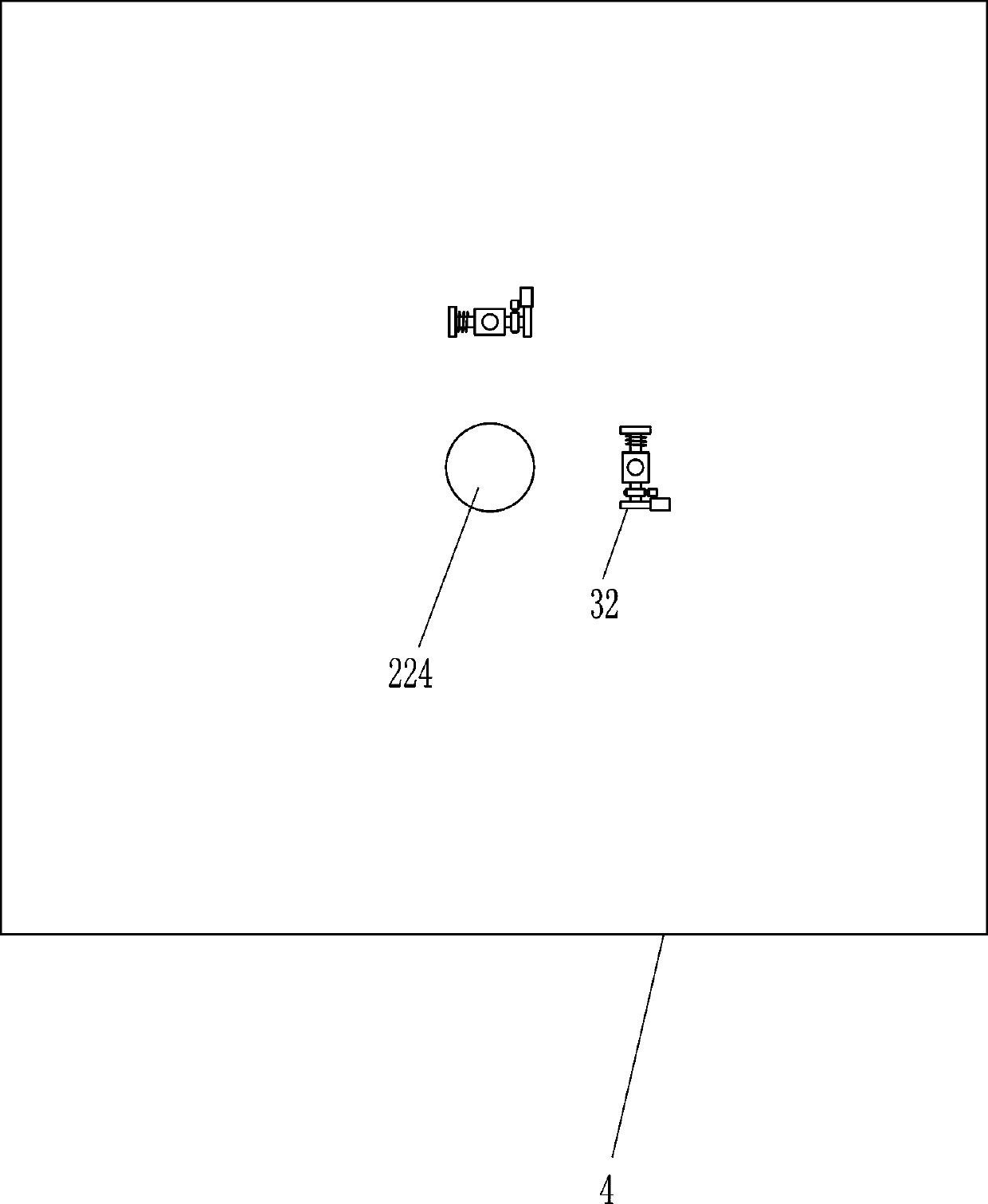
[0021] A portable workpiece tapping machine, such as Figure 1-9As shown, it includes a bottom plate 1, a spacer 2, a mounting plate 3, a fixing plate 4, a guide rod 6, a pressure block 7, a connecting rod 8, a first nut 9, a mounting rod 10, a first bearing seat 11, a first wire Rod 12, gear motor 13, handle 14, control box 15, control board 16, main switch 17, up switch 18, down switch 19, tapping switch 191, rotating rod 21, coupling sleeve 22, second nut 222 , fixed shaft 223, tap 224, hexagon socket screw 226, guide rail 23, guide sleeve 24, connecting plate 25, second bearing block 26, drive motor 27, first travel switch 28 and second travel switch 29, the top of base plate 1 Spacers 2 are connected to the front, rear, left, and right sides, and spacers 2 are connected to the top, front, rear, left, and right sides of the bottom plate 1. The right side of the bottom plate 1 is connected to the mounting plate 3, and the left side of the mounting plate 3 is connected to th...
Embodiment 2
[0023] A portable workpiece tapping machine, such as Figure 1-9 As shown, it includes a bottom plate 1, a spacer 2, a mounting plate 3, a fixing plate 4, a guide rod 6, a pressure block 7, a connecting rod 8, a first nut 9, a mounting rod 10, a first bearing seat 11, a first wire Rod 12, gear motor 13, handle 14, control box 15, control board 16, main switch 17, up switch 18, down switch 19, tapping switch 191, rotating rod 21, coupling sleeve 22, second nut 222 , fixed shaft 223, tap 224, hexagon socket screw 226, guide rail 23, guide sleeve 24, connecting plate 25, second bearing block 26, drive motor 27, first travel switch 28 and second travel switch 29, the top of base plate 1 Blocks 2 are connected to the front, rear, left, and right sides, the mounting plate 3 is connected to the right side of the bottom plate 1, the fixing plate 4 is connected to the left side of the mounting plate 3, and the first guide holes 5 are opened on the front, rear, left, and right sides of ...
Embodiment 3
[0026] A portable workpiece tapping machine, such as Figure 1-9 As shown, it includes a bottom plate 1, a spacer 2, a mounting plate 3, a fixing plate 4, a guide rod 6, a pressure block 7, a connecting rod 8, a first nut 9, a mounting rod 10, a first bearing seat 11, a first wire Rod 12, gear motor 13, handle 14, control box 15, control board 16, main switch 17, up switch 18, down switch 19, tapping switch 191, rotating rod 21, coupling sleeve 22, second nut 222 , fixed shaft 223, tap 224, hexagon socket screw 226, guide rail 23, guide sleeve 24, connecting plate 25, second bearing block 26, drive motor 27, first travel switch 28 and second travel switch 29, the top of base plate 1 Blocks 2 are connected to the front, rear, left, and right sides, the mounting plate 3 is connected to the right side of the bottom plate 1, the fixing plate 4 is connected to the left side of the mounting plate 3, and the first guide holes 5 are opened on the front, rear, left, and right sides of ...
PUM
Abstract
The invention relates to a workpiece tapping machine, in particular to a portable type workpiece tapping machine. The portable type workpiece tapping machine aims to achieve the technical effects of achieving automatic tapping, saving labor and being convenient to move. According to the technical scheme, the portable type workpiece tapping machine comprises a base plate, cushion blocks, an installation plate, a fixing plate, guide rods, press blocks, connection rods, first nuts, installation rods, first bearing seats, first lead screws, speed reduction motors and the like. The front side, theback side, the left side and the right side of the top of the base plate are all connected with the cushion blocks. The installation plate is connected with the right side of the base plate. The leftside of the installation plate is connected with the fixing plate. The front side, the back side, the left side and the right side of the fixing plate are all provided with first guide holes. According to the portable type workpiece tapping machine, rotation of screw tap can be achieved through the speed reduction motors, so that it is not needed to manually rotate the screw tap; workers can conveniently carry the portable type workpiece tapping machine in the manner of holding a handle; due to arrangement of an air pump and an electronic control valve, automatic vertical movement of the screwtap can be achieved, the situation that the screw tap is vertically moved through manpower is not needed, and the intelligence degree of the portable type workpiece tapping machine is improved.
Description
technical field [0001] The invention relates to a workpiece tapping machine, in particular to a portable workpiece tapping machine. Background technique [0002] In the field of construction, it is often necessary to tap some workpieces in order to install the workpieces. Now when tapping the workpieces, if the workpieces are small, the workpieces are generally tapped manually by turning the taps, because tapping requires a large This will greatly reduce the tapping efficiency. If the workpiece is large, it needs to be transported to a larger tapping equipment for tapping, which is very inconvenient. Contents of the invention [0003] In order to overcome the disadvantages of relying on manpower for tapping small workpieces and carrying the workpieces for tapping large workpieces, the technical problem is to provide a portable workpiece tapping that can realize automatic tapping, save manpower, and is convenient to move. wire machine. [0004] The technical solution is: ...
Claims
Application Information
Patent Timeline
Application Date:The date an application was filed.
Publication Date:The date a patent or application was officially published.
First Publication Date:The earliest publication date of a patent with the same application number.
Issue Date:Publication date of the patent grant document.
PCT Entry Date:The Entry date of PCT National Phase.
Estimated Expiry Date:The statutory expiry date of a patent right according to the Patent Law, and it is the longest term of protection that the patent right can achieve without the termination of the patent right due to other reasons(Term extension factor has been taken into account ).
Invalid Date:Actual expiry date is based on effective date or publication date of legal transaction data of invalid patent.

