Eureka AIR delivers breakthrough ideas for toughest innovation challenges, trusted by R&D personnel around the world.

Fan blade propelled wing-in-ground ship

A technology of wing-in-ground effect boats and fan wings, which is applied to seaplanes, aircraft, motor vehicles, etc., can solve the problems of restricting the practicality and commercialization of wing-effect boats, high maintenance costs, and large taxiing impact loads, etc., to achieve improved Sea surface take-off and landing capability, low take-off speed and simple structure

Inactive Publication Date: 2019-02-15
CHINA SHIP SCIENTIFIC RESEARCH CENTER (THE 702 INSTITUTE OF CHINA SHIPBUILDING INDUSTRY CORPORATION)
View PDF7 Cites 4 Cited by
  • Summary
  • Abstract
  • Description
  • Claims
  • Application Information

AI Technical Summary

Problems solved by technology

At present, WIG boats widely used in domestic and foreign markets are mainly small WIG boats (with a take-off weight below 5000kg). lack of
At the same time, there are many disadvantages such as high take-off speed, heavy taxiing impact load, loud propeller noise, low installation position and easy to pump water, etc., which seriously restrict the practical and commercialization of WIG craft.

Method used


Image

  • Fan blade propelled wing-in-ground ship
  • Fan blade propelled wing-in-ground ship
  • Fan blade propelled wing-in-ground ship

Examples


Embodiment Construction

[0017] Specific embodiments of the present invention will be described below.

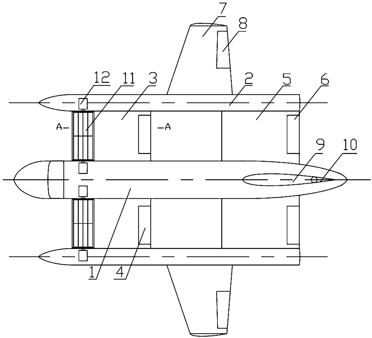
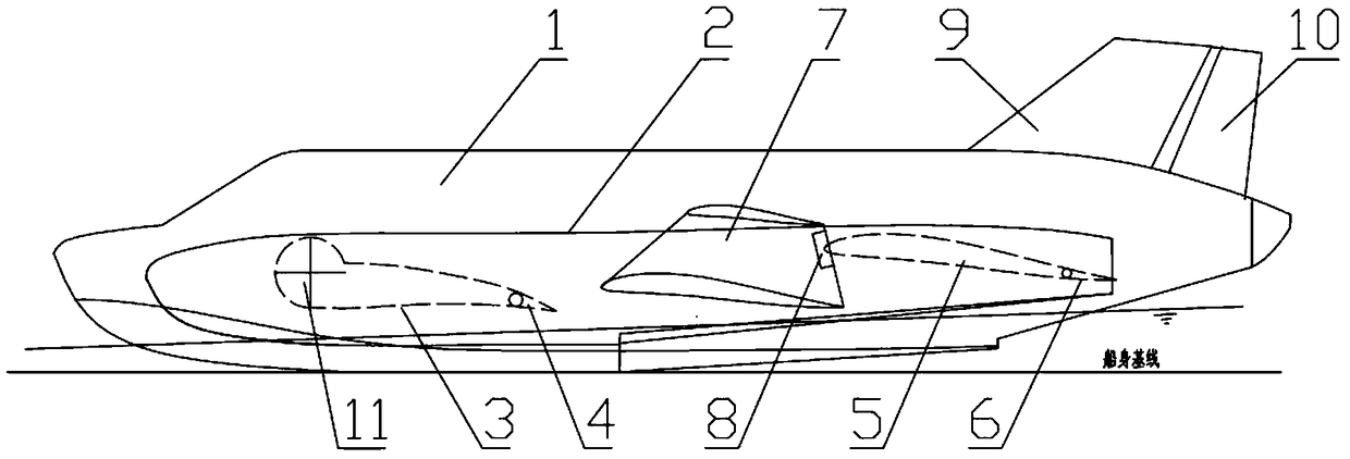
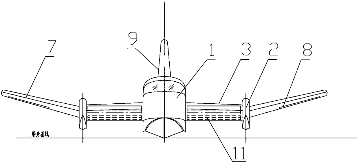
[0018] A fan-wing propelled WIG boat includes a hull 1 for providing the buoyancy of the WIG boat on the water surface, and side buoys 2 are respectively arranged on both sides of the hull 1 for providing the righting moment of water surface heeling. A front wing 3 and a rear wing 5 for providing lift are sequentially arranged between the body 1 and each side pontoon 2 , and a cross-flow fan 11 is also arranged between the hull 1 and each side pontoon 2 at the leading edge of each front wing 3 A diversion plate with an opening is also extended from the end of the front wing 3 close to the cross-flow fan 11. The diversion plate 301 extends outward from one end of the upper surface of the front wing 3 to form an arc-shaped diversion plate. The lower surface ends of the front wings 3 are connected. Flaps 4 are set at the tail edge of each front wing 3, elevators 6 are set at the tail edge of each rea...


PUM


Abstract

The invention relates to a fan blade propelled wing-in-ground ship. The fan blade propelled wing-in-ground ship comprises a ship body; the two sides of the ship body are each provided with a side pontoon; front wings and rear wings are sequentially arranged between the ship body and the side pontoons; a cross-flow fan is also arranged between the front edge of each front wing and between the shipbody and each side pontoon; one end, close to the corresponding cross-flow fan, of each front wing also extends to form a flow guide plate provided with an opening; the edge of the tail of each frontwing is provided with a wing flap; the edge of the tail of each rear wing is provided with an elevator; the outer sides of the side pontoons are each provided with a flank; each flank is provided withan aileron; and the tail of the ship body is further provided with a vertical tail provided with a rudder. The fan blade propelled wing-in-ground ship provided by the invention is simple in structureand convenient to use; the cross-flow fans which are additionally arranged can be used for simultaneously providing elevating force and pushing force for flying of the wing-in-ground ship, thus the sailing noises are reduced; and quite and hidden sailing can be beneficially realized.

Description

technical field [0001] The invention relates to the field of ship design, in particular to a fan-wing propelled WIG ship. Background technique [0002] WIG boats generally adopt a normal aircraft-style aerodynamic layout, with a high-mounted large flat tail. At present, WIG boats widely used in domestic and foreign markets are mainly small WIG boats (with a take-off weight below 5000kg). lack of. At the same time, there are many disadvantages such as high take-off speed, large taxiing impact load, loud propeller noise, low installation position and easy to pump water, which seriously restrict the practical and commercialization of wing-in-ground effect ships. Contents of the invention [0003] In view of the above-mentioned existing problems, the applicant has carried out research and improvement, and provides a fan-wing propelled WIG boat. By installing a cross-flow fan on the leading edge of the wing of the WIG boat, it can simultaneously provide the WIG boat with a T...

Claims


Application Information

Patent Timeline
Patent Type & Authority Applications(China)
IPC IPC(8): B64C35/00
CPCB64C35/006
Inventor 邢福渠继东查建波
Owner CHINA SHIP SCIENTIFIC RESEARCH CENTER (THE 702 INSTITUTE OF CHINA SHIPBUILDING INDUSTRY CORPORATION)
Why Eureka
Eureka Blog
Learn More