Substrate splitting device

A technology for substrates and slivers, applied in glass cutting devices, glass manufacturing equipment, manufacturing tools, etc., can solve the problem of easily scratched display panels, chuck synchronization, difficult to control the clamping angle and height, and the falling of residual materials. Out of sync, etc.

Active Publication Date: 2019-02-15
SHENZHEN CHINA STAR OPTOELECTRONICS SEMICON DISPLAY TECH CO LTD
View PDF3 Cites 3 Cited by
  • Summary
  • Abstract
  • Description
  • Claims
  • Application Information

AI Technical Summary

Problems solved by technology

[0003] In a prior art, chucks are used to pick up residual materials, because it is difficult to control parameters such as the synchronization of the chucks, the clamping angle, and the clamping height, so it is easy to scratch the display panel, causing the display panel to be scrapped
In another prior art, a roller is used

Method used


Image

  • Substrate splitting device

Examples


Embodiment Construction

[0019] In order to make the above and other objectives, features, and advantages of the present disclosure more comprehensible, preferred embodiments of the present disclosure will be exemplified below in detail with reference to the attached drawings. Furthermore, the direction terms mentioned in this disclosure, such as up, down, top, bottom, front, back, left, right, inside, outside, side layer, surrounding, center, horizontal, transverse, vertical, longitudinal, axial , radial direction, the uppermost layer or the lowermost layer, etc., are only directions for referring to the attached drawings. Therefore, the directional terms used are used to explain and understand the present disclosure, but not to limit the present disclosure.

[0020] In the figures, structurally similar units are denoted by the same reference numerals.

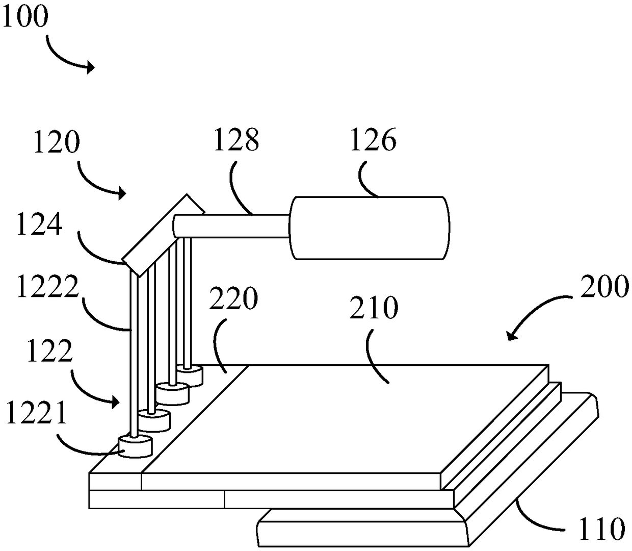
[0021] refer to figure 1 , a substrate splitting device 100 according to an embodiment of the present disclosure includes a stage 110 and a splitt...


PUM


Abstract

The invention provides a substrate splitting device. The substrate splitting device comprises a stage and a splitting structure. The stage is used for carrying a plurality of substrates. Each substrate comprises a body and a residue. The splitting structure comprises a plurality of spacer members, a connecting member and a driving member. The connecting member connects the spacer members and the driving member. The drive member is used for driving the spacer members to apply multi-point pressure to the residues, so that the residues are broken from the bodies. The multi-point pressure is applied to the residues by the spacer members, so that the residues are stressed uniformly at a unified time, and the asynchronization of falling of the residues and the damage to the bodies of the substrates can be avoided.

Description

【Technical field】 [0001] The disclosure relates to the field of display technology, in particular to a substrate splitting device. 【Background technique】 [0002] In order to meet different usage requirements, the size of the display panel varies with the requirements. Therefore, during the processing of the display panel, it needs to go through the process of cutting and slicing, that is, in order to obtain the required specifications, a larger piece of glass The substrate is cut and divided into plates that meet the predetermined size. When cutting the lobes, first use the cutting knife to draw the cutting line on the glass substrate fixed on the working platform, then move the glass substrate to another working platform, and use the break bar to apply appropriate pressure to the glass substrate. Stress, so that it is divided into two halves along the cutting line due to the stress, and the above steps are repeated until the glass substrate meets the predetermined size. ...

Claims


Application Information

Patent Timeline
IPC IPC(8): C03B33/033
CPCC03B33/033
Inventor 王伟曹河江
Owner SHENZHEN CHINA STAR OPTOELECTRONICS SEMICON DISPLAY TECH CO LTD
Why Eureka
Try Eureka