Hank tie knotting device used for hank reeling machine

A technology of knotting device and spinning machine, which is applied in knotting, other manufacturing equipment/tools, textiles and papermaking, etc. It can solve the difficulty in achieving consistent lengths of twisted strands, cracked finger skin, and poor quality of manual twisting. and other issues to achieve the effect of improving the efficiency and quality of stranding

Pending Publication Date: 2019-02-15
张家港市塘桥镇鹿苑鑫森纺纱厂
View PDF0 Cites 7 Cited by
  • Summary
  • Abstract
  • Description
  • Claims
  • Application Information

AI Technical Summary

Problems solved by technology

[0003] Traditionally, the manual twisting method is adopted. The workers twist the multiple skeins on the rotary yarn frame in turn, so there is a problem of low efficiency, and when the tying is done, the operator inserts his fingers into the yarns of the skeins. Long-term operation is likely to cause finger skin cracks, etc., and there is a certain degree of risk of injury to workers, which further reduces production efficiency, and the length of the stranded wire after knotting is affected by the operator's proficiency, height and machine. Due to the influence of relative height, it is difficult to achieve the same length of stranded wires for manual tying. Therefore, the quality of manual tying cannot be guaranteed. If automatic tying can be used, production efficiency can be effectively improved and the risk of injury to workers can be avoided. , reduce the working intensity of the car operator, and can effectively control the length of each stranded wire to improve the quality of the skeined yarn

Method used


Image

  • Hank tie knotting device used for hank reeling machine
  • Hank tie knotting device used for hank reeling machine
  • Hank tie knotting device used for hank reeling machine

Examples


Embodiment Construction

[0028] Specific embodiments of the present invention will be described in detail below in conjunction with the accompanying drawings.

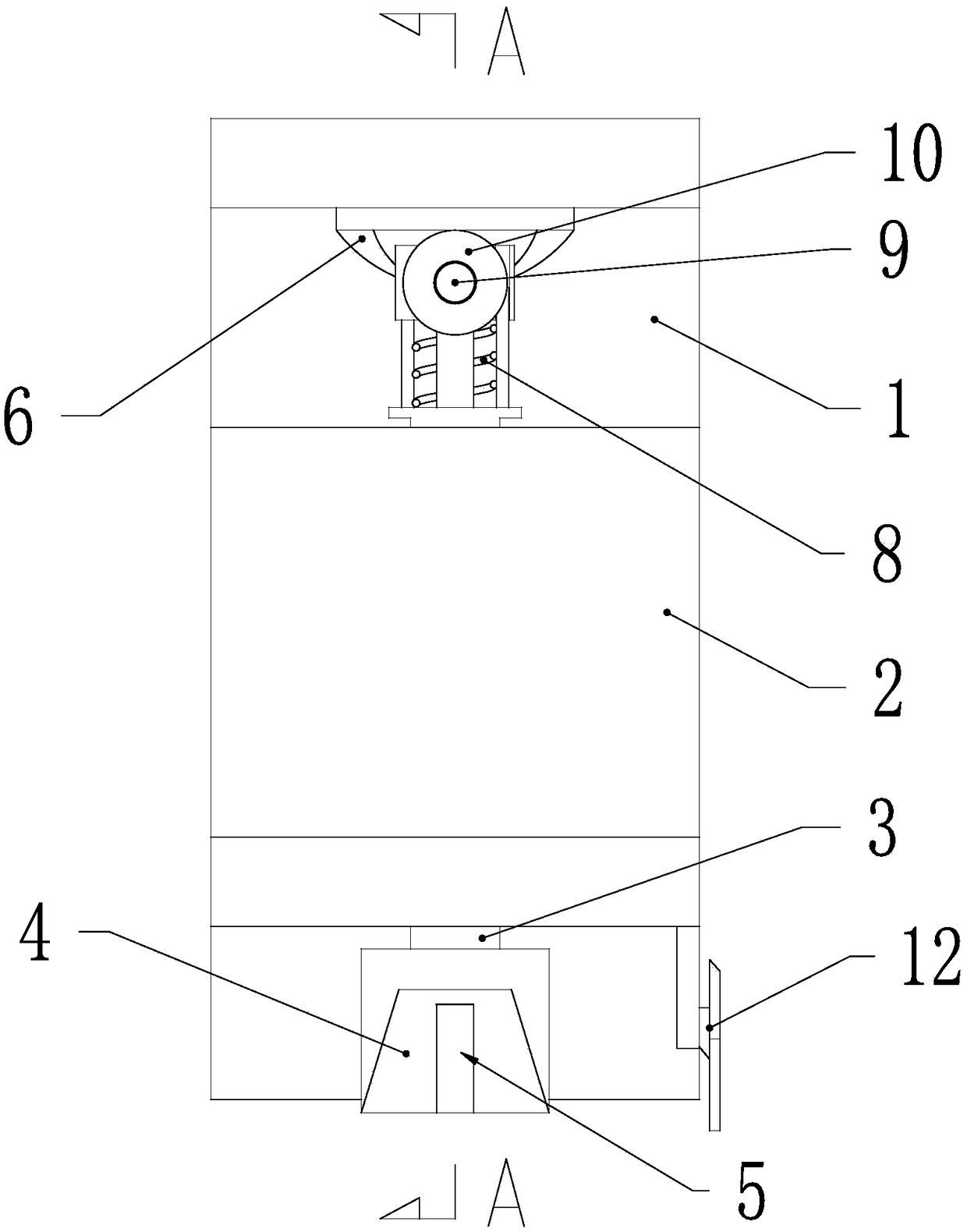
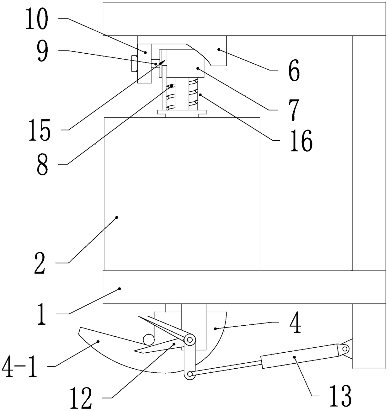
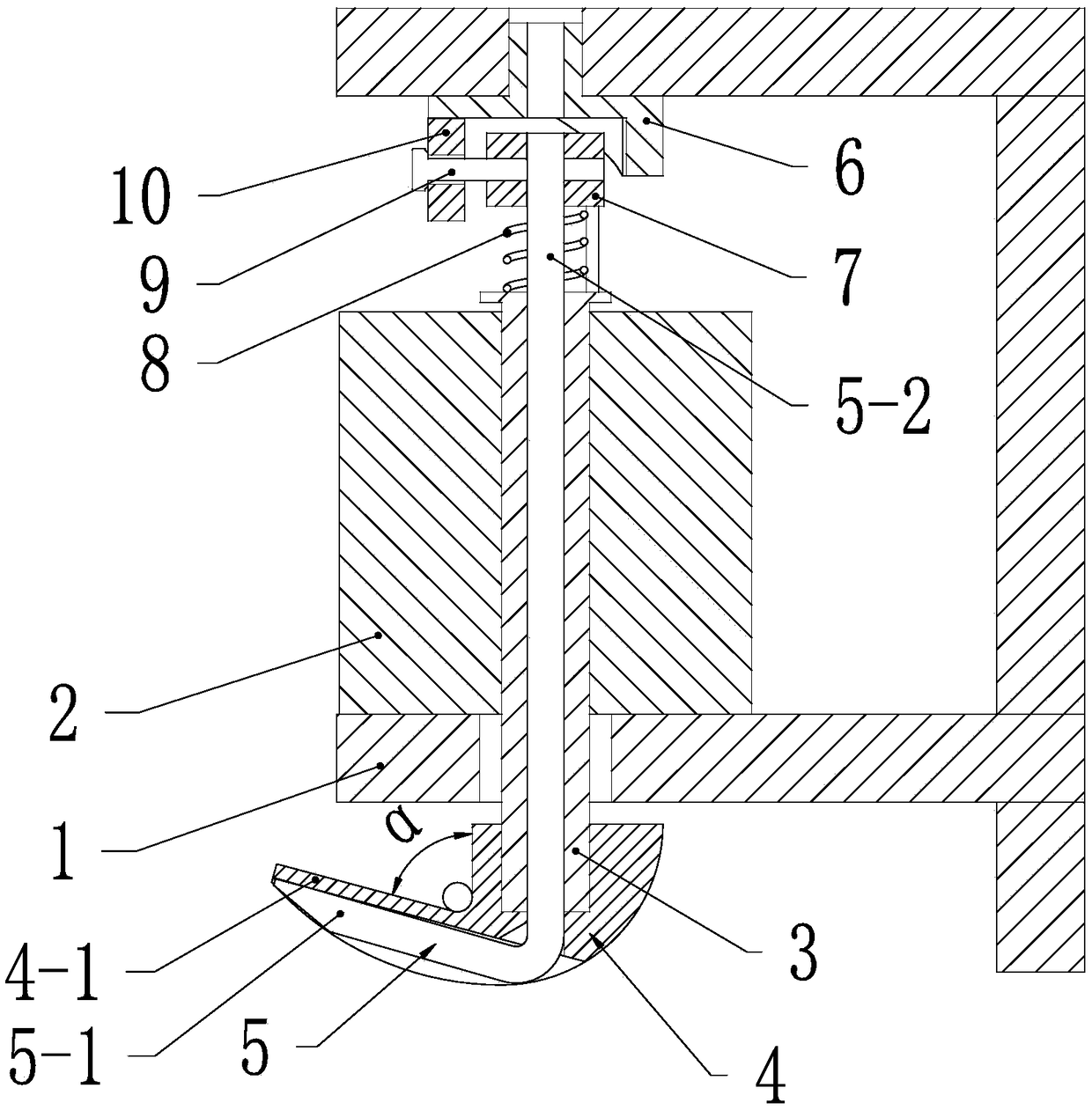
[0029] Such as Figure 1 ~ Figure 4 Shown is a twisted wire knotting device applied to a spinning machine, including a frame 1, a hollow shaft motor 2 is fixedly connected to the frame 1, and the motor 2 is a servo motor or a stepping motor or an ordinary motor with an encoder. The motor, the rotating shaft 3 of the motor 2 is a hollow shaft, and one end of the rotating shaft 3 of the motor 2 is connected with a knotting hook 4, the angle α between the inner surface of the fixed hook head 4-1 of the knotting hook 4 and the rotating shaft 3 is an acute angle, and the rotating shaft 3 is coaxially provided with a clamping hook 5, which includes a movable hook head 5-1 and a hook handle 5-2 connected to each other, and the hook handle 5-2 can be axially slidably plugged in the In the central hole, both ends of the hook handle 5-2 are stretched o...


PUM


Abstract

The invention relates to a hank tie knotting device used for a hank reeling machine. The hank tie knotting device comprises a rack, a hollow-shaft motor is fixedly connected with the rack, one end ofa rotary shaft of the motor is connected with a knotting hook, a thread clamping hook is coaxially arranged in the rotary shaft, the thread clamping hook comprises a movable hook head and a hook handle which are mutually connected, the hook handle can slide axially and is inserted into a central hole of the rotary shaft, the two ends of the hook handle stretch out of the rotary shaft, the movablehook head and the knotting hook are arranged at the same end of the rotary shaft, and the movable hook head of the thread clamping hook is located on the outer side of a fixed hook head of the knotting hook. The rack is further provided with a driving mechanism used for driving the thread clamping hook to move forth and back in the axial direction of the rotary shaft, and the thread clamping hookand the rotary shaft synchronously rotate. By means of the knotting device, a hank tie can be automatically knotted, after automation is achieved, the positions of knots of all the hank ties are same,the lengths of the hank ties are equal, and the hank tie quality is improved.

Description

Technical field: [0001] The invention relates to a knotting device, in particular to a twisting wire knotting device applied to a spinning machine. Background technique: [0002] Yarn shaker, also known as shaker, is a machine that winds the bobbin on the rotary yarn frame to form a twist. N mutually dispersed positions are twisted, and each position divides the coiled yarn into N strands, and then uses a stranding wire to pass through the N strands of yarn and then knots, so that the original coiled yarn is divided into N strands separated from each other. Strands to avoid coiled skein winding, which is beneficial to the processing of the subsequent process. [0003] Traditionally, the manual twisting method is adopted. The workers twist the multiple skeins on the rotary yarn frame in turn, so there is a problem of low efficiency, and when the tying is done, the operator inserts his fingers into the yarns of the skeins. Long-term operation is likely to cause finger skin c...

Claims


Application Information

Patent Timeline
Patent Type & Authority Applications(China)
IPC IPC(8): D04G5/00D02H11/00
CPCD04G5/00D02H11/00
Inventor 姚鑫森
Owner 张家港市塘桥镇鹿苑鑫森纺纱厂
Why Eureka
Try Eureka