a floating device

A technology of floating devices and fluid control devices, which is applied to engine components, machines/engines, and ocean energy power generation. Device cost, the effect of reducing the mass of the float

Active Publication Date: 2020-09-04
CHENGDU UNIVERSITY OF TECHNOLOGY
View PDF7 Cites 0 Cited by
  • Summary
  • Abstract
  • Description
  • Claims
  • Application Information

AI Technical Summary

Problems solved by technology

[0004] The purpose of the present invention is to provide a floating device with large buoyancy, small mass and high utilization rate of wave energy used in wave energy utilization, so as to solve the related technical problems existing in existing floats

Method used


Image

  • a floating device
  • a floating device
  • a floating device

Examples


Embodiment Construction

[0034] In order to make the objectives, technical solutions, and advantages of the present invention clearer, the present invention will be further described in detail below in conjunction with specific embodiments and with reference to the accompanying drawings. It is worth mentioning that these descriptions are only exemplary and are not intended to limit the scope of application of the present invention.

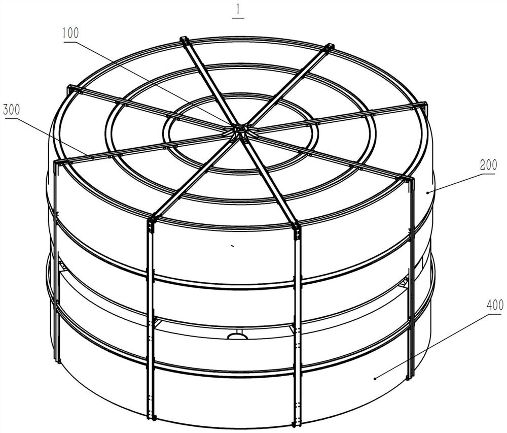
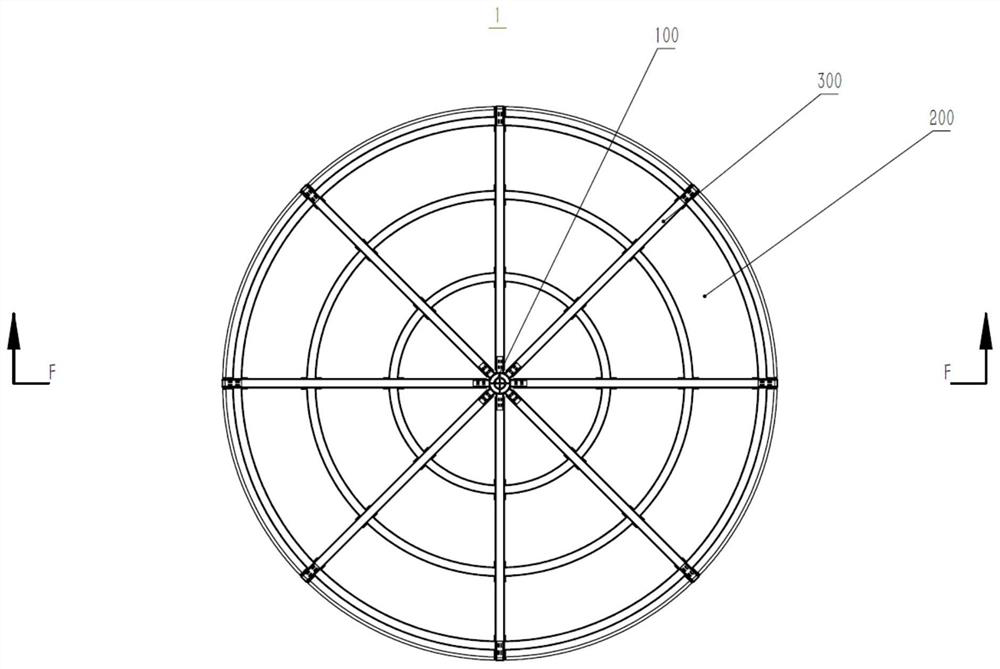
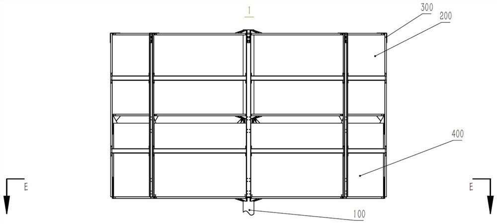
[0035] The floating device 1 floats on the surface of the fluid by the buoyancy received by the float 200. Since the fluid containing part 400 is located below the float 200, the fluid containing part 400 is filled with fluid at this time. When there are undulating waves in the fluid, the float 200 is acted on by buoyancy during the rising phase of the waves and drives the floating device 1 to rise along with the waves. During the descent phase of the wave, since the movement of the floating device lags behind the wave, the fluid in the fluid containing portion 400 cannot fl...


PUM


Abstract

The invention discloses a floating device. The floating device is used for utilizing wave energy. The floating device mainly comprises a rod assembly 100, a floater 200, a frame assembly 300 and a fluid containing part 400; the fluid containing part 400 is located below the floater 200 and floats up and down together with the floater along with waves formed by a fluid; and at a wave ascending stage, the fluid can enter the fluid containing part, and at a wave descending stage, the fluid containing part can prevent the fluid from flowing out of the fluid containing part. Thus, according to thefloating device, at the wave descending stage, energy input can be provided for an external device through the gravity of the fluid contained in the fluid containing part, the wave energy utilizing rate can be increased, and thus the cost of the floating device is lowered.

Description

Technical field [0001] The invention relates to a floating device using wave energy. Background technique [0002] A wave energy generating device is a device that converts the mechanical motion of waves into electrical energy. There are many types of wave energy power generation devices. Among them, the floating direct-drive wave energy power generation device is a new type of power generation device that converts wave energy into electrical energy through a linear motor, which is mainly composed of an oscillating float and a linear generator. The floating direct-drive wave energy device uses the fluctuation of the float to drive the linear motor mover to reciprocate up and down, and directly converts wave energy into electric energy without complicated intermediate conversion devices such as gearboxes and hydraulic systems, so it has high reliability and low maintenance. [0003] The existing single-unit large-capacity floating direct-drive wave energy power generation device us...

Claims


Application Information

Patent Timeline
Patent Type & Authority Patents(China)
IPC IPC(8): F03B13/20
CPCF03B13/20Y02E10/30
Inventor 荆海莲任晓晨刘伟张雨潇
Owner CHENGDU UNIVERSITY OF TECHNOLOGY
Why Eureka
Try Eureka