Intelligent glasses with heat-dissipating function
A technology of smart glasses and functions, which is applied in the directions of glasses/goggles, optics, instruments, etc. It can solve the problems that the mirror legs cannot be stopped, affect the rotation effect, and the screws are loose, so as to achieve the appropriate temperature of the body and realize the cooling effect. The effect of preventing loosening
- Summary
- Abstract
- Description
- Claims
- Application Information
AI Technical Summary
Problems solved by technology
Method used
Image
Examples
Embodiment 1
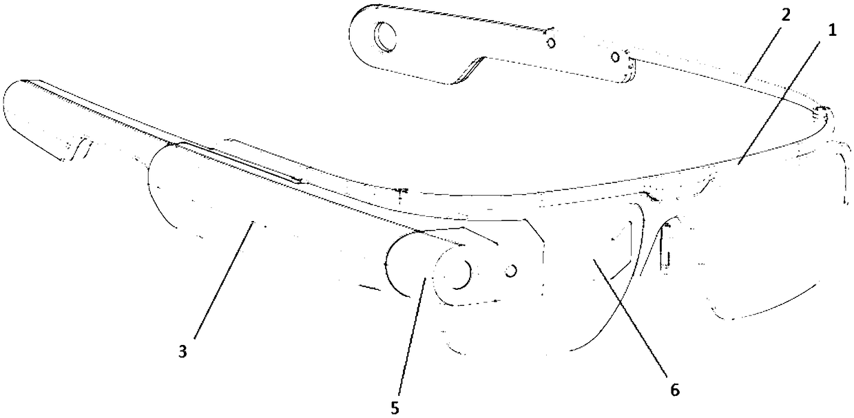
[0025] Embodiment 1: see attached figure 2 , a kind of smart glasses with heat dissipation function, which includes: a lens frame 1, temples 2, a host 3, a broadcaster 4, a camera 5 and a display screen 6;
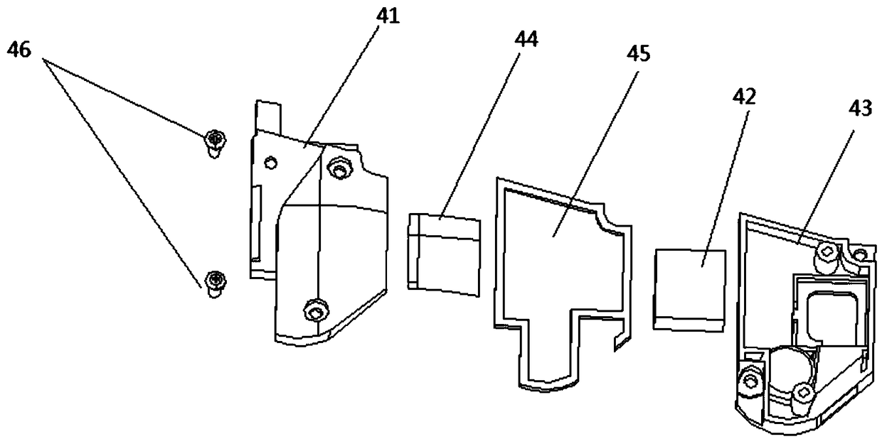
[0026] See attached image 3 , the broadcaster 4 includes: an aluminum alloy upper cover 41, a speaker 42 and a plastic lower cover 43; the speaker 42 is installed in the plastic lower cover 43 through a mylar sheet 44; Afterwards, tighten and fix by screw 46;
[0027] See attached Figure 4 , 5 , the host 3 includes: a main housing made up of a left housing 31 and a right housing 32, and a left cooling fin 33, a right cooling fin 34, a copper-aluminum cooling fin 35, a main board 36, and a second cooling fin arranged in the main housing. A heat-conducting silica gel 37, a second heat-conducting silica gel 38, and a heat sink connecting plate 39; wherein, the left heat sink 33 is attached to the inner wall of the left housing 31, and the right heat sink 34 is attached...
Embodiment 2
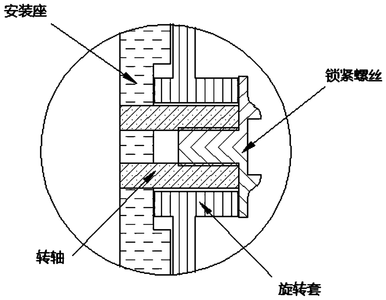
[0029] Embodiment 2: see attached Figure 7 , on the basis of Embodiment 1, in order to realize the stop of the rotation of the mirror legs at any angle, the mirror legs 2 are connected to the lens frame 1 through the rotating shaft 7, the rotating sleeve 8, the locking screw 9 and the damping gasket 10; wherein, the rotating shaft 7 One end is plugged into the mounting seat of the lens frame 1, and the other end is provided with a locking screw 9; the rotating sleeve 8 is sleeved on the rotating shaft 7, and the two ends of the rotating sleeve 8 pass through the damping gasket 10 and the mounting seat of the lens frame 1 respectively. , The locking screw 9 is in contact; the mirror leg 2 is connected with the rotating sleeve 8 . When the locking screw 9 is locked, the swivel sleeve 8 generates friction with the lens frame 1 through the damping washer 10 to form resistance, so that the rotation of the mirror legs can be stopped at any angle.
Embodiment 3
[0030] Embodiment 3: see attached Figure 8 , 9 , on the basis of Embodiment 1, in order to prevent the locking screw 9 from loosening, the mirror leg 2 is connected to the lens frame 1 through the rotating shaft 7, the rotating sleeve 8, the locking screw 9 and the locking washer 11; wherein, One end of the rotating shaft 7 is plugged into the mounting seat of the lens frame 1, and the other end is provided with a polygonal protrusion 71; the locking washer 11 is provided with a polygonal hole matching the polygonal protrusion 71; the locking washer 11 is sleeved on the polygonal On the protrusion 71; the lower end surface of the locking screw 9 is in conflict with the locking washer 11, and is threadedly connected with the rotating shaft 7; the rotating sleeve 8 is sleeved on the rotating shaft 7; When the mirror leg 2 rotates, the rotating sleeve 8 will only contact the locking washer 11 and will not contact the locking screw 9, so as to avoid the loosening of the screw. ...
PUM
 Abstract
Description
Claims
Application Information
 - R&D
- Intellectual Property
- Life Sciences
- Materials
- Tech Scout
- Unparalleled Data Quality
- Higher Quality Content
- 60% Fewer Hallucinations
Browse by: Latest US Patents, China's latest patents, Technical Efficacy Thesaurus, Application Domain, Technology Topic, Popular Technical Reports.
© 2025 PatSnap. All rights reserved.Legal|Privacy policy|Modern Slavery Act Transparency Statement|Sitemap|About US| Contact US: help@patsnap.com


