Inspection robot fixed-point inspection method

An inspection robot and robot technology, applied in the field of inspection robots, can solve problems such as poor practicability and inconvenient laying, and achieve the effect of expanding the work area

Inactive Publication Date: 2019-02-15
杭州合时机器人科技有限公司
View PDF4 Cites 7 Cited by
  • Summary
  • Abstract
  • Description
  • Claims
  • Application Information

AI Technical Summary

Problems solved by technology

[0003] In the existing inspection scheme, the navigation scheme of the inspection robot is basically to lay magnetic guide rails and magnetic strips throug

Method used


Image

  • Inspection robot fixed-point inspection method
  • Inspection robot fixed-point inspection method
  • Inspection robot fixed-point inspection method

Examples


Embodiment Construction

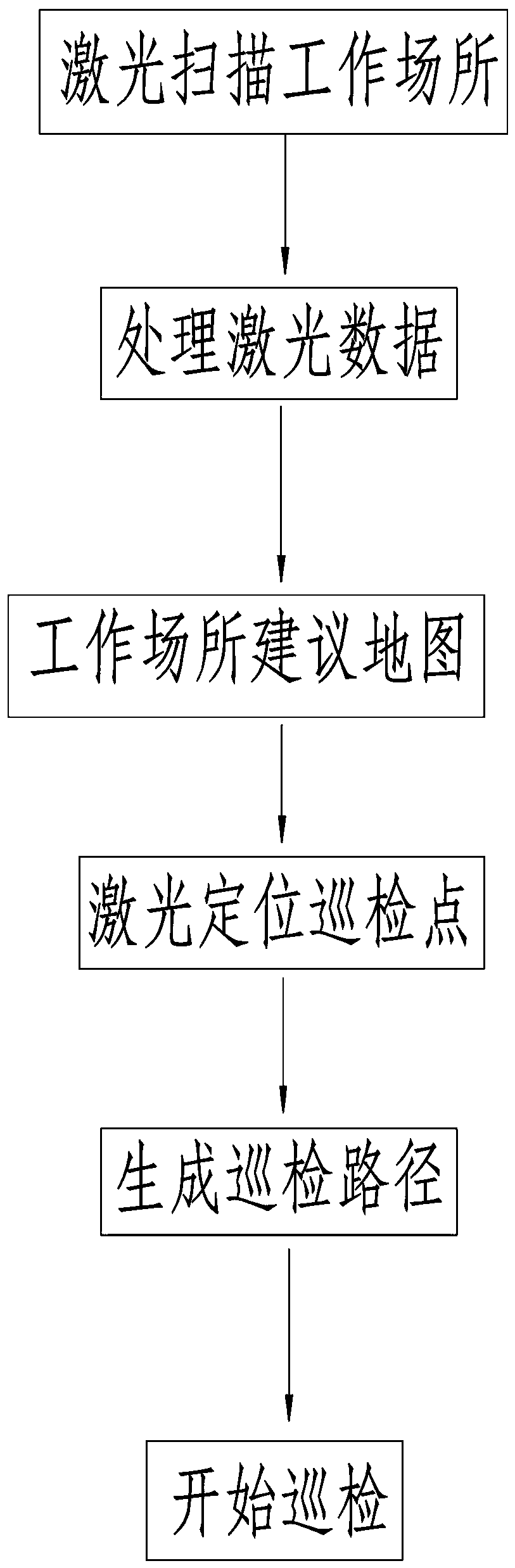
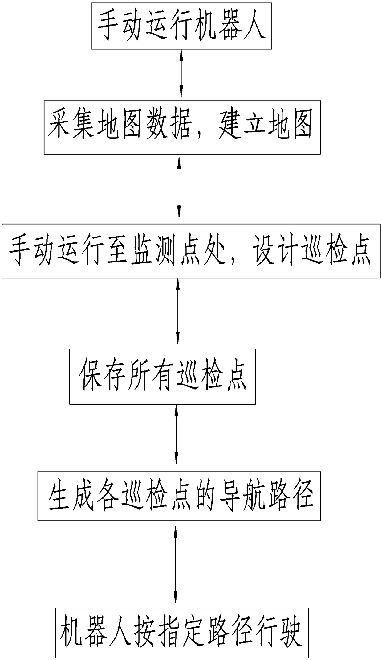
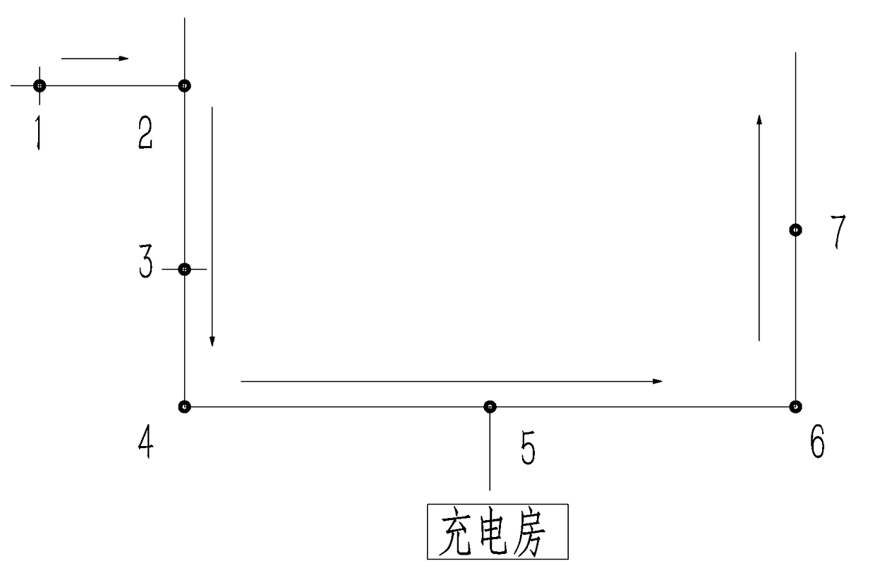
[0018] refer to Figure 1-3 , a fixed-point inspection method for an inspection robot, the steps of which include the following:

[0019] A: Install a laser scanner on the front of the robot, run the robot manually in the workplace, make the laser scanner on the robot scan the workplace and record the laser scanning data;

[0020] B: Build a map of the workplace based on laser scanning data and determine the origin of the robot's operation;

[0021] C: Run the robot to the inspection point that needs to be monitored, determine the current coordinates of the robot according to the laser positioning and save it;

[0022] D: Display the origin and all inspection points on the map, and generate a robot-operable inspection path based on the inspection points, and the robot will run in the workplace according to the specified path.

[0023] In the above method, when the robot is moving forward in the actual running path, the laser locates the current coordinates of the robot, and ...


PUM


Abstract

The invention relates to a fixed-point inspection method for inspection robot, which mainly solves the technical problems of laying magnetic guide rail and magnetic strip for inspection through electromagnetic induction. The technical scheme of the invention includes the following steps: a laser scanner is installed at the front of the robot, and the laser scanner scans the data obtained in the workplace to establish a map; the robot saves coordinate data at the inspection point and forms a fixed-point inspection path on the map according to the saved inspection point; the robot patrols the actual path according to the map path. The invention can specify the position to be detected on the running path by laser.

Description

technical field [0001] The invention relates to the field of inspection robots, and mainly relates to a fixed-point inspection method of an inspection robot. Background technique [0002] With the rapid development of robot technology, various types of robots are widely used in many fields, such as industry, agriculture, social service industry, medical industry, military and so on. The inspection robot is also one of the robots widely used in these fields. The robot is equipped with cameras and other equipment to complete the tasks of workplace monitoring and inspection. The application prospects and practical value of this type of robot are very broad. [0003] In the existing inspection scheme, the navigation scheme of the inspection robot is basically to lay magnetic guide rails and magnetic strips through electromagnetic induction inspection, but for the situation where laying is inconvenient, the practicability of this inspection scheme is relatively poor. Contents o...

Claims


Application Information

Patent Timeline
IPC IPC(8): G05D1/02
CPCG05D1/0231
Inventor 卢秋红刘小蒙
Owner 杭州合时机器人科技有限公司
Why Eureka
Try Eureka