Diode automatic welding wire leading machine

An automatic welding and lead machine technology, applied in electrical components, coupling devices, electrical solid devices, etc., can solve problems such as accidental power failure, poor stability, and hidden safety hazards, and achieve easy operation, improved stability, safety, and structure. simple effect

Inactive Publication Date: 2019-02-15
广州迅速光电科技有限公司
View PDF1 Cites 0 Cited by
  • Summary
  • Abstract
  • Description
  • Claims
  • Application Information

AI Technical Summary

Problems solved by technology

[0002] The diode automatic wire welding machine is widely used in the field of welding. It needs to be connected to the mains during use, while the power supply pieces in the traditional power supply stand are all connected to the outside. During the welding process, accidental contact It will cause electric shock accidents after touching, and there is a great potential safety hazard. At the same time, the stability of the traditional automatic wire welding machine is poor when the power supply is connected, which often causes unexpected power failures, which brings great changes to the welding use.

Method used


Image

  • Diode automatic welding wire leading machine
  • Diode automatic welding wire leading machine

Examples


Embodiment Construction

[0020] All features disclosed in this specification, or steps in all methods or processes disclosed, may be combined in any manner, except for mutually exclusive features and / or steps.

[0021] Any feature disclosed in this specification (including any appended claims, abstract and drawings), unless expressly stated otherwise, may be replaced by alternative features which are equivalent or serve a similar purpose. That is, unless expressly stated otherwise, each feature is one example only of a series of equivalent or similar features.

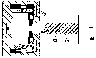
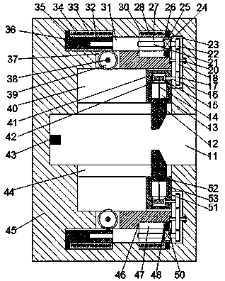
[0022] Such as Figure 1-2 As shown, a diode automatic wire welding machine of the device of the present invention includes a socket 10 and a plug joint 60 connected to the welding machine, and the left and right of the socket 10 are extended and provided with a sliding cavity 11 with an opening facing the right , the upper and lower end walls of the sliding joint cavity 11 are symmetrically provided with first sliding joint grooves 40, and a...


PUM


Abstract

The invention discloses a diode automatic welding wire leading machine. The diode automatic welding wire leading machine comprises an inserting-connecting base and an inserting-connecting head connected with a welding machine; a sliding-connecting cavity with a rightward through opening is formed in the inserting-connecting base in a left-and-right extension mode; first sliding-connecting groovesare symmetrically formed in the upper end wall and the lower end wall of the sliding-connecting cavity; a through-connection groove is formed between each first sliding-connecting groove and the sliding-connecting cavity in a communication mode; a first sliding-connecting block is arranged in the first sliding-connecting groove in a sliding-connecting mode; a telescopic groove, with a through opening towards the through-connection groove, is formed in the first sliding-connecting block; a slope locking block which penetrates through the through-connection groove and extends into the sliding-connecting cavity is arranged in the telescopic groove in a sliding-connecting mode; a first adapter cavity is formed in the end wall, far away from the through-connection groove, of the telescopic groove in a connection mode; a first adapter shaft is rotationally mounted in the left end wall and the right end wall of the first adapter cavity; the first adapter shaft is fixedly provided with a winding wheel, and the winding wheel is wound with a connecting rope; and one end, far from the winding wheel, of the connecting rope is fixedly connected with the slope locking block.

Description

technical field [0001] The invention relates to the technical field of welding, in particular to a diode automatic wire welding machine. Background technique [0002] The diode automatic wire welding machine is widely used in the field of welding. It needs to be connected to the mains during use, while the power supply pieces in the traditional power supply stand are all connected to the outside. During the welding process, accidental contact It will cause electric shock accidents after touching, and there is a great potential safety hazard. At the same time, the stability of the traditional automatic wire welding machine is poor when the power supply is connected, which often causes unexpected power failures, which brings great changes to welding. Contents of the invention [0003] Aiming at the deficiencies of the above-mentioned technologies, the present invention proposes a diode automatic wire welding machine. [0004] A diode automatic welding lead wire machine of t...

Claims


Application Information

Patent Timeline
Patent Type & Authority Applications(China)
IPC IPC(8): H01R13/627H01R13/633H01R13/635H01R13/639H01R13/70H01L21/60
CPCH01R13/639H01L24/78H01L2224/78H01R13/6278H01R13/633H01R13/635H01R13/701
Inventor 黄均杰
Owner 广州迅速光电科技有限公司
Why Eureka
Try Eureka