Optical module

A technology of optical modules and lasers, applied in the field of optical modules, can solve problems such as inability to adapt to ns-level burst time performance index requirements

Active Publication Date: 2019-02-15
HISENSE BROADBAND MULTIMEDIA TECH
View PDF6 Cites 0 Cited by
  • Summary
  • Abstract
  • Description
  • Claims
  • Application Information

AI Technical Summary

Problems solved by technology

Therefore, the existing OLT cannot meet the performance index requirements of ns-level burst time

Method used


Image

  • Optical module
  • Optical module
  • Optical module

Examples


Embodiment Construction

[0017] The optical module provided by this application enables the optical line terminal optical module to have the performance of ns-level burst transmission and burst reception, and promotes the realization of uniform use of one optical module in a passive optical network.

[0018] In order to make the object, technical solution and advantages of the present invention clearer, the present invention will be further described in detail below in conjunction with the accompanying drawings and embodiments. It should be understood that the specific embodiments described here are only used to explain the present invention, not to limit the present invention.

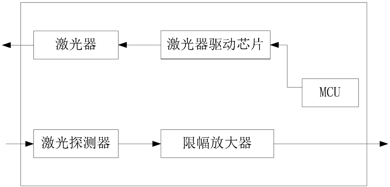
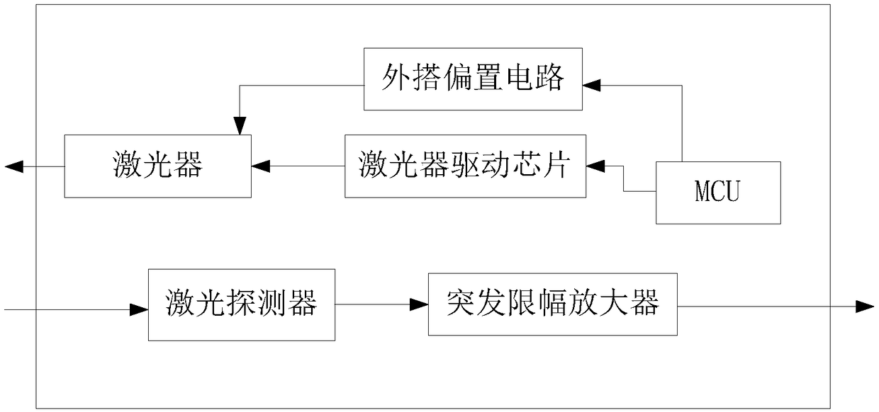
[0019] The optical module provided in the embodiment of the present application is used for passive optical networks. The optical module provided in the embodiment of the present application is similar to the function of the traditional OLT optical module, and has the function of burst reception, but it also has a burst turn-o...


PUM


Abstract

The invention provides an optical module. The optical module comprises a laser and an externally established bias circuit. An input end of the externally established bias circuit is connected with anMCU of the optical module. An output end of the externally established bias circuit is connected with a laser. The externally established bias circuit comprises an operational amplifier, an MOS transistor and a control switch which are connected in sequence. The input end of the operational amplifier is connected with the MCU. The output end of the operational amplifier is connected with a gate ofthe MOS transistor. The operational amplifier is used for amplifying a voltage which is output by the MCU to the gate of the MOS transistor and improving a voltage adjustment range of the gate of theMOS transistor. A source of the MOS transistor is connected with a power supply. A drain of the MOS transistor is connected with the input end of the control switch. The output end of the control switch is connected with the laser. The control switch receives a burst signal. The control switch switches on the laser according to the burst signal. According to the optical module provided by the invention, the optical line terminal optical module has ns-level burst transmitting and burst receiving performance.

Description

technical field [0001] The present application relates to the technical field of optical communication equipment, and in particular to an optical module. Background technique [0002] With the growth of people's demand for communication, fiber optic access (FTTx) has been developed rapidly. Optical fiber access technology based on passive optical network (Passive Optical Network, PON) technology has been widely used in various forms around the world. PON means that ODN (Optical Distribution Network) does not contain any electronic devices and electronic power sources. ODN is composed of passive devices such as optical splitters and does not require expensive active electronic devices. A passive optical network includes an optical line terminal (Optical Line Terminal, OLT) installed in the central control station, and a batch of supporting optical network units (Optical Network Unit, ONU) installed in the user's place. [0003] However, in long-term use, operators and equip...

Claims


Application Information

Patent Timeline
Patent Type & Authority Applications(China)
IPC IPC(8): H04B10/40H04B10/50
CPCH04B10/40H04B10/503
Inventor 赵其圣闫洪平薛登山
Owner HISENSE BROADBAND MULTIMEDIA TECH
Why Eureka
Try Eureka