
A message sending method, device, network device and computer-readable medium

A technology for network equipment and message sending, applied in data exchange networks, digital transmission systems, electrical components, etc., can solve problems affecting IPL, affecting the stability of DR systems, etc., to improve bandwidth usage, ensure stability, and reduce transparent transmission. Effect

Active Publication Date: 2021-05-07
XINHUASAN INFORMATION TECH CO LTD
View PDF11 Cites 0 Cited by
  • Summary
  • Abstract
  • Description
  • Claims
  • Application Information

AI Technical Summary

Problems solved by technology

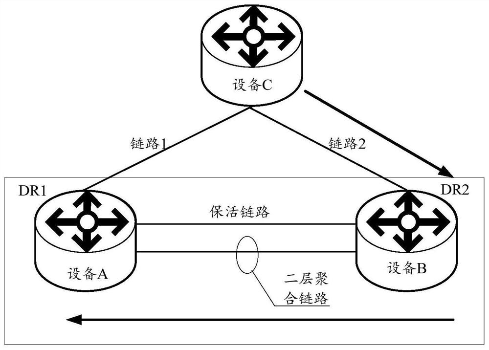
If it is PVST (Per-VLAN SpanningTree, each VLAN spanning tree) mode, when a large number of VLANs are enabled, a large number of PVST protocol packets will be sent, and a large number of protocol packets will be transparently transmitted to device A on device B, so that It will affect the bandwidth usage of the IPL (Intra-Portal Link, internal control link) link, and even affect the stability of the DR system

Method used


Image

  • A message sending method, device, network device and computer-readable medium
  • A message sending method, device, network device and computer-readable medium
  • A message sending method, device, network device and computer-readable medium

Examples


Embodiment Construction

[0028] In order to make the purpose, technical solutions and advantages of the embodiments of the present disclosure clearer, the technical solutions of the present disclosure will be clearly and completely described below in conjunction with the accompanying drawings. Apparently, the described embodiments are part of the embodiments of the present disclosure, not all of them. the embodiment. Based on the embodiments in the present disclosure, all other embodiments obtained by persons of ordinary skill in the art without creative efforts fall within the protection scope of the present disclosure.

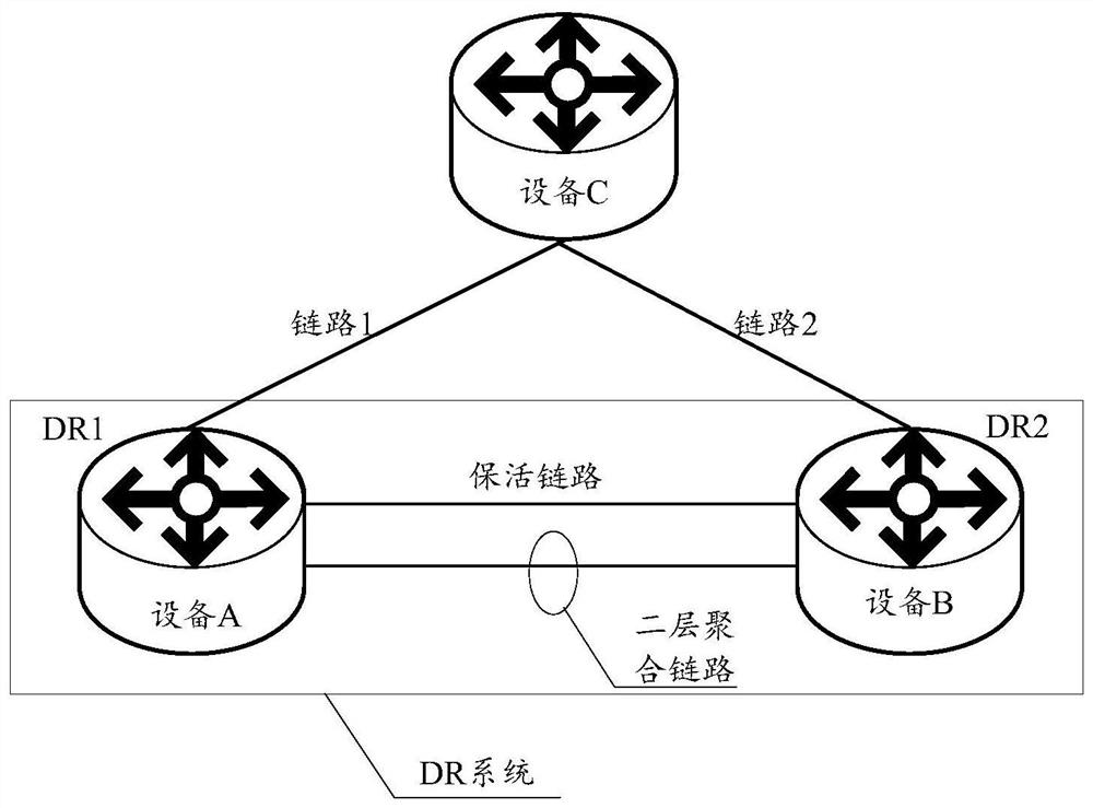
[0029] In a typical DRNI network, two physical devices are aggregated through Ethernet links to form a DR system. On the network, the DR system appears as a device to the outside world.

[0030] Such as figure 1 As shown, the DR system includes the following parts:

[0031]DR device (Distributed Relay device, distributed aggregation member device): DR devices are physical devices...


PUM


Abstract

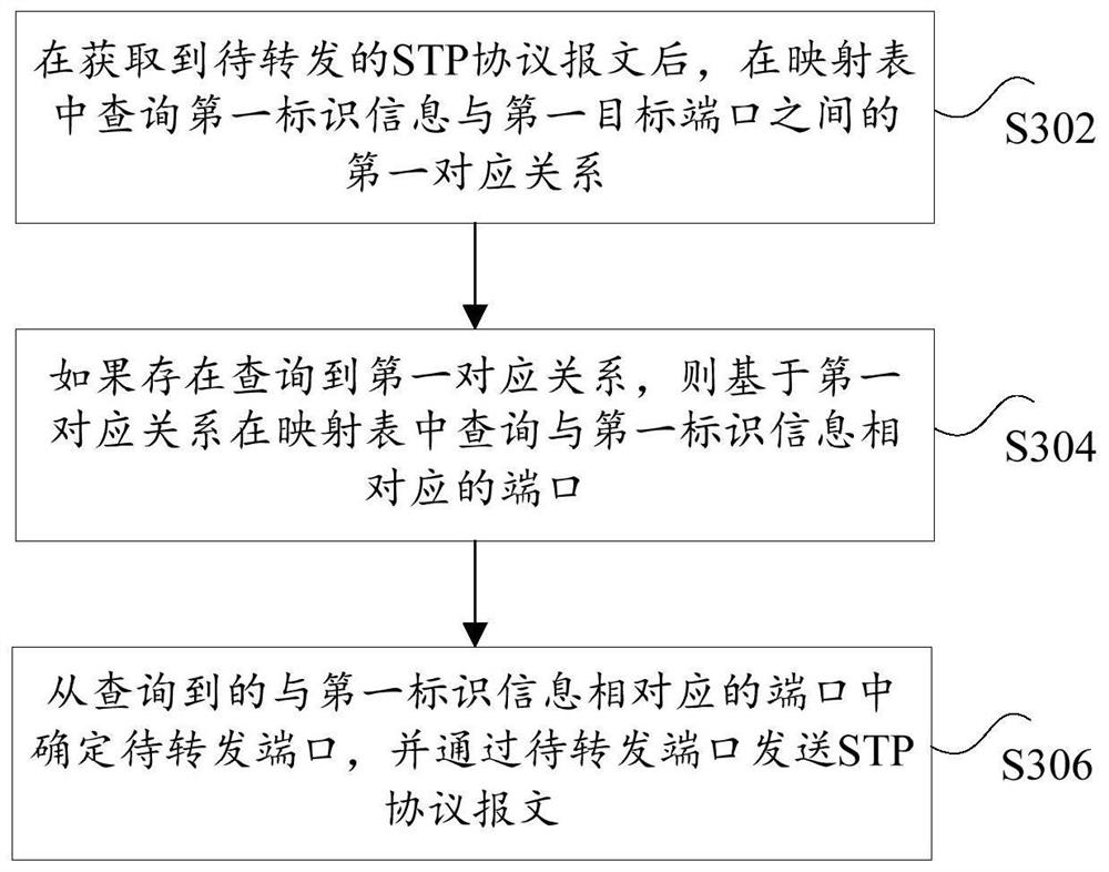
The present disclosure provides a message sending method, device, network equipment, and computer-readable medium, and relates to the technical field of communication equipment, including: after obtaining the STP protocol message to be forwarded, querying the first identification information and the first A first correspondence between target ports, wherein the first target port is a port in the master DR device corresponding to the first identification information that is connected to the network device in communication; if the first correspondence is found, based on the first correspondence Querying the port corresponding to the first identification information; determining the port to be forwarded from the queried ports corresponding to the first identification information, and sending the STP protocol message through the port to be forwarded. The disclosure is used to forward the STP protocol message through the main DR device, so as to reduce the transparent transmission of the protocol message, improve the bandwidth usage of the IPL link, and ensure the stability of the DR system.

Description

technical field [0001] The present disclosure relates to the technical field of communication equipment, and in particular, to a message sending method, device, network equipment, and computer-readable medium. Background technique [0002] DRNI (Distributed Resilient Network Interconnect, Distributed Aggregation) technology connects two physical devices to virtualize a logical device through Ethernet link aggregation, realizing inter-device link aggregation. Among them, the real-time synchronization data is aggregated between the two physical devices that form the distributed aggregation through the Ethernet link, providing device-level redundancy protection. In a typical RNI network, two physical devices are aggregated through Ethernet links to form a DR system (Distributed-Relay System, distributed aggregation system). [0003] Such as figure 1 As shown, after the DR system is established normally, when the aggregation port on the C device selects the port to send the ST...

Claims


Application Information

Patent Timeline
Patent Type & Authority Patents(China)
IPC IPC(8): H04L12/709H04L12/935H04L45/243H04L49/111
CPCH04L45/245H04L49/30
Inventor 刘永奎王伟
Owner XINHUASAN INFORMATION TECH CO LTD
Learn More