Testing systems and methods, terminals and computer memory medium

A technology for testing systems and terminals to be tested, which is applied in transmission systems, signal transmission systems, transmitter monitoring, etc., and can solve problems such as low testing efficiency, high cost, and increased manpower

Active Publication Date: 2019-02-15
OPPO CHONGQING INTELLIGENT TECH CO LTD
View PDF7 Cites 4 Cited by
  • Summary
  • Abstract
  • Description
  • Claims
  • Application Information

AI Technical Summary

Problems solved by technology

[0003] The existing solution can divide the pop-up state and the retracted state into two steps for testing, and the antenna performance in the retracted state and the antenna performance in the pop-up state can be tested in turn. Although this solution is

Method used


Image

  • Testing systems and methods, terminals and computer memory medium
  • Testing systems and methods, terminals and computer memory medium
  • Testing systems and methods, terminals and computer memory medium

Examples


Embodiment 1

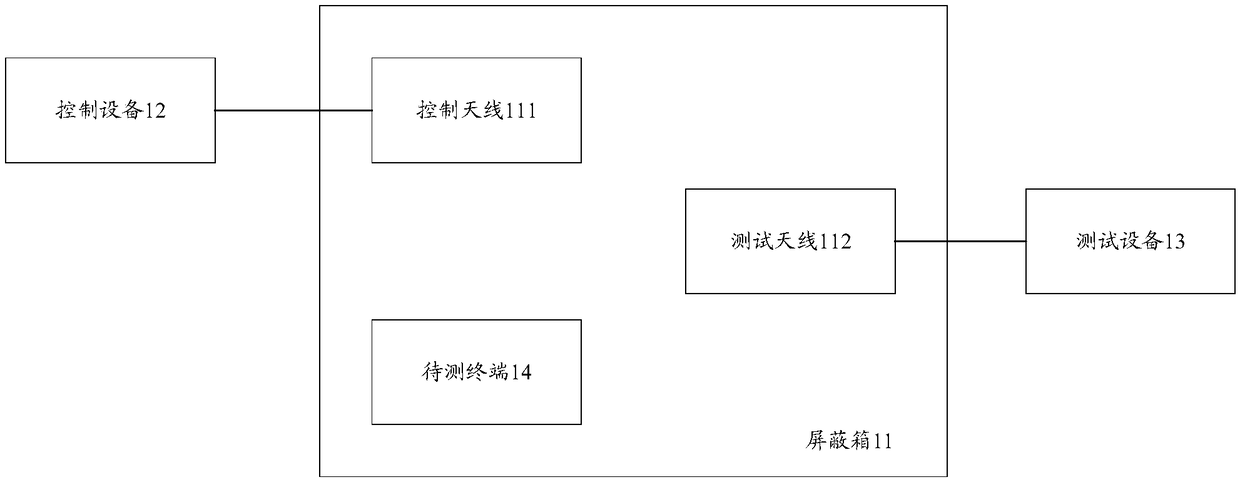
[0055] The embodiment of the present application provides a test system, figure 1 For a schematic structural diagram of an optional test system provided in the embodiment of this application, refer to figure 1 As shown, the test system may include: a shielding box 11, a control device 12 and a test device 13;

[0056]Wherein, the shielding box 11 includes a control antenna 111 and a test antenna 112, the shielding box 111 is used to place the terminal 14 to be tested with the antenna to be tested; the control device 12 is connected to the control antenna 111, and the test device 13 is connected to the test antenna 112; The control device 12 establishes a WLAN connection with the terminal under test 14 through the control antenna 111 based on the generated wireless local area network (WLAN, Wireless Local Area Networks) signal;

[0057] The control device 12 is configured to generate a control signal, and send the control signal to the terminal under test 14 through the contro...

Embodiment 2

[0115] Based on the above test method on the test system side, the test method will be described below on the side of the terminal to be tested.

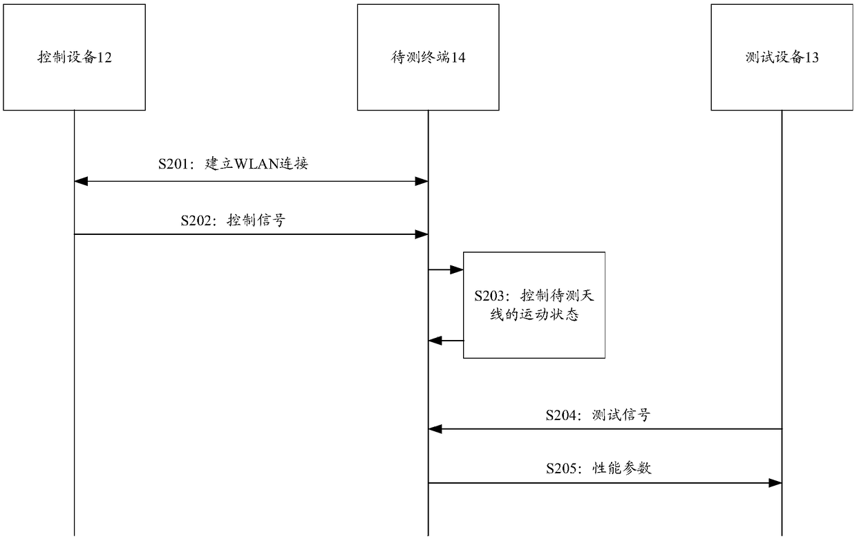
[0116] Figure 5 For a schematic flow diagram of an optional testing method provided in the embodiment of the present application, refer to Figure 5 As shown, the method is applied to a terminal under test of a test system, and the test system may include: a shielding box, control equipment, and test equipment; the terminal to be tested is placed in a shielding box, and the shielding box includes a control antenna and a test antenna; The control device is connected to the control antenna, and the test device is connected to the test antenna; the control device establishes a WLAN connection with the terminal under test through the control antenna based on the generated WLAN signal; the test method may include:

[0117] S501: receiving a control signal from a control device;

[0118] S502: Control the motion state of the antenna un...


PUM


Abstract

The embodiments of the invention disclose testing systems. A testing system comprises a shielding box, control equipment and testing equipment. The shielding box comprises a control antenna and a testing antenna. The shielding box is used for placing a to-be-tested terminal with a to-be-tested antenna. The control equipment is connected with the control antenna. The testing equipment is connectedwith the testing antenna. The control equipment establishes WLAN connection with the to-be-tested terminal based on a generated WLAN signal through utilization of the control antenna. The control equipment is used for generating a control signal and sending the control signal to the to-be-tested terminal through utilization of the control antenna. The to-be-tested terminal is used for controllinga motion state of the to-be-tested antenna according to the control signal. The testing equipment is used for generating a testing signal, sending the testing signal to the to-be-tested terminal through utilization of the testing antenna, testing the to-be-tested antenna in a current motion state and obtaining performance parameters of the to-be-tested antenna. The embodiments of the invention also provide testing methods, the terminals and a computer memory medium.

Description

technical field [0001] The present application relates to a testing technology of an antenna of a terminal, and in particular to a testing system, a method, a terminal and a computer storage medium. Background technique [0002] Mobile phone pop-up antenna, that is, the mobile phone antenna is built into the mobile phone body. In some special cases, for example, when the base station signal received by the mobile phone is weak, the built-in antenna can be controlled by a motor to automatically extend out. Finally, the signal of the mobile phone can be enhanced. Then, in order to ensure that the retracted and popped-up state of the antenna is good, it is necessary to test the performance of the antenna in the pop-up and retracted states. [0003] The existing solution can divide the pop-up state and the retracted state into two steps for testing, and the antenna performance in the retracted state and the antenna performance in the pop-up state can be tested in turn. Although ...

Claims


Application Information

Patent Timeline
IPC IPC(8): H04W76/10G08C17/02H04W24/08H04B17/10
CPCG08C17/02H04W24/08H04B17/101H04W76/10
Inventor 刘振腾
Owner OPPO CHONGQING INTELLIGENT TECH CO LTD
Why Eureka
Try Eureka