Wig winding device

A winding device and wig technology, applied in wigs, clothing, applications, etc., can solve the problems of inconvenient disassembly and assembly of winding rollers, difficult control of winding thickness, and limited scope of application, etc.

Active Publication Date: 2019-02-19
河南壹通智能科技有限公司
View PDF5 Cites 4 Cited by
  • Summary
  • Abstract
  • Description
  • Claims
  • Application Information

AI Technical Summary

Problems solved by technology

[0002] Wigs are hair made by artificial technology and are used for decorative accessories. In the process of wig production, a winding device is required to wind the wig. The thickness of the existing wig winding device is not easy to control. The length of the roller is fixed and the winding roller is not easy to disassemble and assemble. It is impossible to replace the winding roller with a suitable length according to the actual production needs, which reduces the production efficiency and limits the scope of application. Therefore, it is urgent to design a simple and easy-to-operate Wig winding device with control of winding speed and thickness, convenient disassembly and installation of winding rollers of different lengths, high production efficiency, wide application range, suitable for mass production

Method used


Image

  • Wig winding device
  • Wig winding device
  • Wig winding device

Examples


Embodiment 1

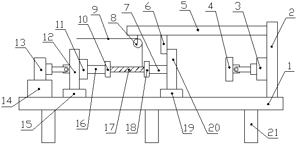
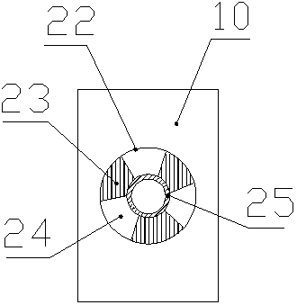
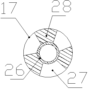
[0018] Such as Figure 1-3 As shown, a wig winding device includes a base 1, the lower end of the base 1 is equipped with a leg 21, the upper end of the base 1 is provided with a slideway, and the upper end of the base 1 is slidably connected with a Slider A15 and slider B19, the slider B19 is located on the right side of the slider A15, the left side of the upper end of the base 1 is fixedly connected with a support base 14, and the upper end of the support base 14 is fixedly equipped with a hydraulic cylinder A13 , the right end of the piston rod of the hydraulic cylinder A13 is connected to the installation column A12, the lower end of the installation column A12 is fixedly connected to the slider A15, and the middle part of the right end of the installation column A12 is fixedly installed with the drive motor 11, the described The output end of the driving motor 11 is connected with a rotating shaft A16, the right end of the rotating shaft A16 is fixedly connected with a f...

Embodiment 2

[0021] Such as Figure 1-3 As shown, a wig winding device includes a base 1, the lower end of the base 1 is equipped with a leg 21, the upper end of the base 1 is provided with a slideway, and the upper end of the base 1 is slidably connected with a Slider A15 and slider B19, the slider B19 is located on the right side of the slider A15, the left side of the upper end of the base 1 is fixedly connected with a support base 14, and the upper end of the support base 14 is fixedly equipped with a hydraulic cylinder A13 , the right end of the piston rod of the hydraulic cylinder A13 is connected to the installation column A12, the lower end of the installation column A12 is fixedly connected to the slider A15, and the middle part of the right end of the installation column A12 is fixedly installed with the drive motor 11, the described The output end of the driving motor 11 is connected with a rotating shaft A16, the right end of the rotating shaft A16 is fixedly connected with a f...


PUM


Abstract

The invention discloses a wig winding device. The wig winding device comprises a base, the upper end of the base is slidingly connected with a slider A and a slider B, the left of the upper end of thebase is connected with a support base, the upper end of the support base is provided with a hydraulic cylinder A, the right end of the piston rod of the hydraulic cylinder A is connected with a mounting column A, the lower end of the mounting column is connected with the slider A, the middle of the right end of the mounting column A is provided with a driving motor, the output end of the drivingmotor is connected with a rotating shaft A, and the right end of the rotating shaft A is connected with a fixing block A; the upper end of the slider B is connected with a mounting column B, the middle of the left end of the mounting column is rotatingly connected with a rotating shaft B, and the left end of the rotating shaft B is connected with a fixing block B; the middle of the right end of the fixing block A and the middle of the left end of the fixing block B are provided with clamping grooves, and a winding roller is clamped inside the clamping grooves; the right of the upper end of thebase is connected with a stand column, the bottom of the left end of the stand column is provided with a hydraulic cylinder B, and the left end of the piston rod of the hydraulic cylinder B is connected with a push plate. The wig winding device has the advantages of being capable of controlling the winding speed and thickness, facilitating assembly and disassembly winding rollers of different lengths and achieving a wide application range.

Description

technical field [0001] The invention relates to the technical field of wig production equipment, in particular to a wig winding device. Background technique [0002] Wigs are hair made by artificial technology and are used for decorative accessories. In the process of wig production, a winding device is required to wind the wig. The thickness of the existing wig winding device is not easy to control. The length of the roller is fixed and the winding roller is not easy to disassemble and assemble. It is impossible to replace the winding roller with a suitable length according to the actual production needs, which reduces the production efficiency and limits the scope of application. Therefore, it is urgent to design a simple and easy-to-operate Wig winding device that controls winding speed and thickness, facilitates disassembly and installation of winding rollers of different lengths, high production efficiency, wide application range, and is suitable for mass production. ...

Claims


Application Information

Patent Timeline
Patent Type & Authority Applications(China)
IPC IPC(8): A41G3/00
CPCA41G3/0075
Inventor 李敬旭
Owner 河南壹通智能科技有限公司
Why Eureka
Try Eureka