Multifunctional closestool

A multi-functional, toilet technology, which is applied to flushing equipment with water tanks, water supply devices, buildings, etc., can solve the problems of hygienic use of buttons and other problems, and achieve the effect of reasonable and compact structure design.

Active Publication Date: 2019-02-19
日照新睿招商发展有限公司
View PDF17 Cites 4 Cited by
  • Summary
  • Abstract
  • Description
  • Claims
  • Application Information

AI Technical Summary

Problems solved by technology

On the other hand, with the increase of toilet functions, the buttons used for control also increase, and there are defects in the use of buttons.

Method used


Image

  • Multifunctional closestool
  • Multifunctional closestool
  • Multifunctional closestool

Examples


Embodiment 1

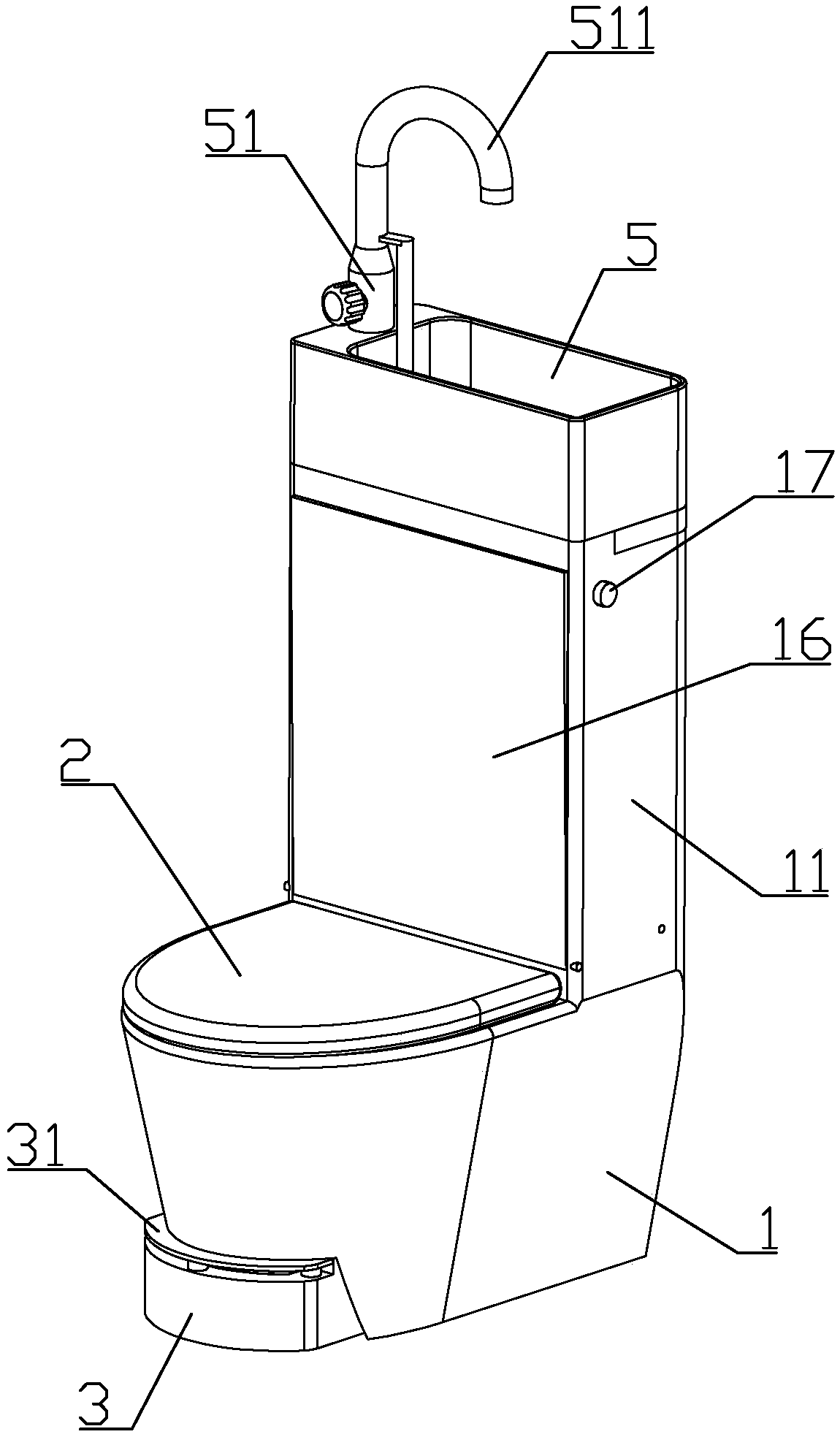
[0091] combine Figure 1 to Figure 10 As shown, the present embodiment provides a multifunctional toilet, including a toilet body 1, the rear side of the toilet body is a water storage tank part 11; toilet seat 2. The toilet body is integrally formed of ceramic materials.

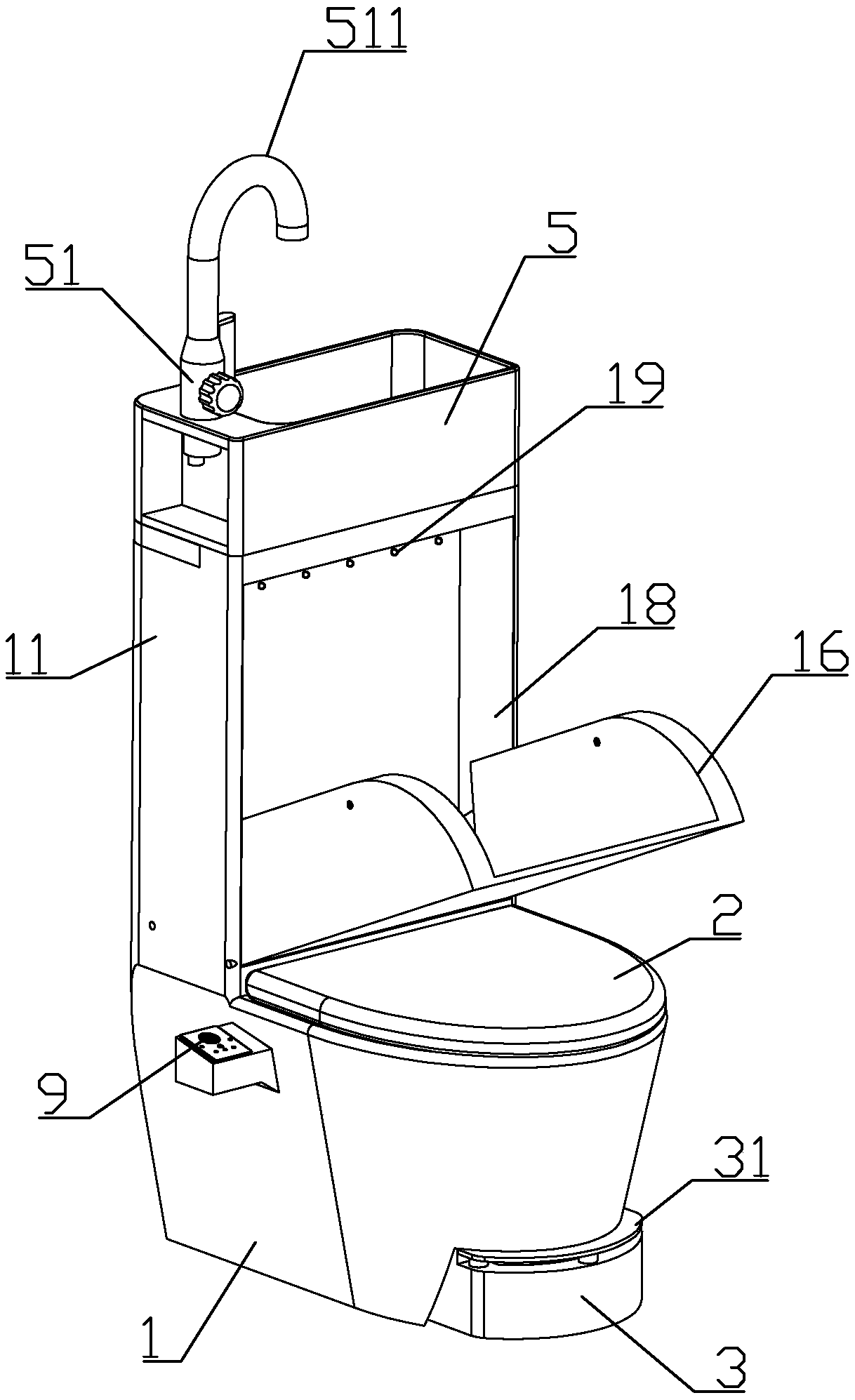
[0092] The front part of the water storage tank is formed with a urinal 18 with a front opening, the lower end of the urinal is a concave receiving groove 182, and the bottom of the receiving trough communicates with the sewer through a pipe; the lower end of the front side of the urinal rotates A cover plate 16 capable of closing the front side of the urinal is connected.

[0093] Two side baffles 161 are symmetrically formed on both sides of the cover plate, and a baffle cavity 181 matching the side baffles is formed on the rear side of the urinal.

[0094] The lower ends of the two side baffles are formed with upwardly extending cavities 162, and a switch for controlling the opening and closing of the...

Embodiment 2

[0121] This embodiment makes the following improvements on the basis of Embodiment 1: an air inlet is formed at a position higher than the air suction port in the inner extension or at a position equal to the air suction port, and the air inlet and the air suction port are positioned along the circumferential direction of the toilet trough The phases are staggered; the toilet main body is formed with an air intake passage communicating with the air inlet, and the air intake passage communicates with the outside through the air intake pipe. Or the air intake duct communicates with the indoor space away from the front side of the toilet main body, for example, the inlet of the air intake duct is located in the gap between the rear side of the toilet main body and the wall.

[0122] The continuous suction of the air outlet will form a negative pressure in the range of the toilet. In winter, the air flow from the human buttocks (and thighs) into the toilet will make the user feel c...

Embodiment 3

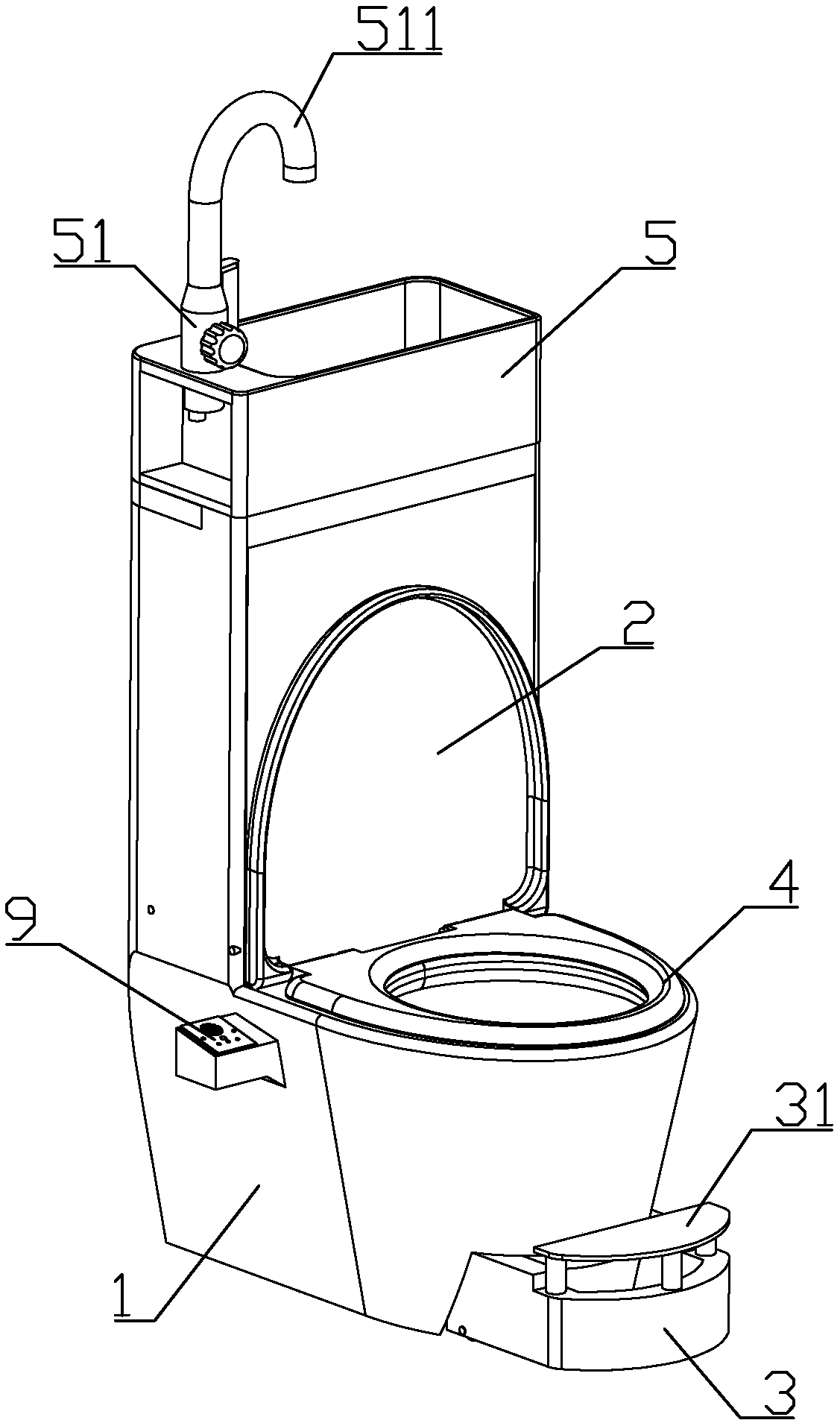
[0124] combine Figure 1 to Figure 14 As shown, this embodiment makes the following improvements on the basis of embodiment 1: the control panel 9 includes a seat body 91 and a panel 92 fixedly connected to the upper end of the seat body.

[0125] The upper part of the panel is formed with three induction air outlets 922 perpendicular to the panel, Every An air outlet pipe 97 is slidably installed in each of the induction air outlets, and a centrifugal fan 95 is installed in the seat, and the air outlet port 951 of the centrifugal fan is connected to one end of each air outlet pipe positioned at the inside of the panel through a hose.

[0126] An air inlet 921 communicating with the air inlet end of the centrifugal fan is formed on the lower part of the panel.

[0127] A sensor mount 923 is formed above the position corresponding to each induction air outlet on the inner wall of the panel, and there is a gap between each sensor mount and the air outlet pipe at the correspondi...


PUM


Abstract

The invention discloses a multifunctional closestool. The multifunctional closestool comprises a closestool body, a water storage box part is arranged on the rear side of the closestool body, a seat ring and a closestool cover are rotationally installed on the portion, on the rear side of a toilet bowl, at the upper end of the closestool body, and a urinal trough with an opening in the front sideis formed in the front portion of the water storage box part; a cover plate capable of blocking the front side of the urinal trough is rotationally connected with the lower end on the front side of the urinal trough, two lateral baffles are symmetrically formed on the two sides of the cover plate, and baffle containing cavities for suitably containing the lateral baffles are formed in the rear side of the urinal trough. Containing grooves extending upwards are formed in the lower ends of the two lateral baffles, hydraulic cylinders are connected between the upper portions of the containing grooves and the lower portions of the baffle containing cavities, and the hydraulic cylinders are driven by the running water pressure to stretch and used for controlling opening and closing of the coverplate. By means of the multifunctional closestool, requirements for urinating of men are met, and the sanitation problems caused when the urine splashes outwards are prevented.

Description

technical field [0001] The invention belongs to the field of toilet structures, and in particular relates to a toilet structure with multiple functions. Background technique [0002] With the improvement of living standards, the functions of toilets are becoming more and more diversified. However, most toilets do not consider the function of facilitating men to urinate, and it is easy to cause urine to splash on the toilet seat, toilet lid or toilet when men urinate. In the case of the outside ground, the effect is not ideal. [0003] In addition, there are currently many toilet seats on the market that have a heating function, so that users do not need to put cotton pads on the seat that are easily polluted in winter; It is convenient for users to step on the footstool to form a squatting posture when going to the toilet, which is good for defecation (especially for users who are used to squatting toilets). On the other hand, along with the increase of toilet functions, t...

Claims


Application Information

Patent Timeline
Patent Type & Authority Applications(China)
IPC IPC(8): E03D5/10E03D1/00E03D1/38
CPCE03D1/003E03D1/38E03D5/105
Inventor 胡良娟
Owner 日照新睿招商发展有限公司
Why Eureka
Try Eureka