Supercharge Your Innovation With Domain-Expert AI Agents!

Full-automatic permanent magnetic telescopic device

A telescopic device, fully automatic technology, applied in the direction of electromechanical devices, electrical components, etc., can solve the problems of complex structure, large volume, large pollution, etc., and achieve the effect of wide application range and small volume

Pending Publication Date: 2019-02-19
HENAN POLYTECHNIC UNIV
View PDF0 Cites 1 Cited by
  • Summary
  • Abstract
  • Description
  • Claims
  • Application Information

AI Technical Summary

Problems solved by technology

The structure is complex and the efficiency is low; the hydraulic cylinder is driven in the form of large volume, troublesome maintenance and pressure maintenance, and large pollution. It is widely used in places with relatively large load-bearing; electromagnetic push rods use the working characteristics of electromagnets, and the suction force is small.

Method used


Image

  • Full-automatic permanent magnetic telescopic device
  • Full-automatic permanent magnetic telescopic device
  • Full-automatic permanent magnetic telescopic device

Examples


Embodiment 1

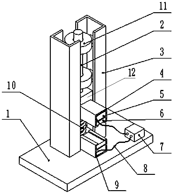
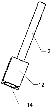
[0025] Fully automatic permanent magnet retractable device, such as figure 1 , 2 , 3, 7, and 8, the device includes a mechanical part, a permanent magnet part and a power supply, and the mechanical part includes a base plate 1, a slideway 3 fixed on the base plate and a spring 10 fixed on the base plate at the center of the slideway. The magnetic part includes two permanent magnet units. The permanent magnet unit includes a permanent magnet holder 9 made of non-magnetic material, a permanent magnet 6, an iron core 5 and a coil 4 wound outside the iron core. The coil is connected to the power supply through a connecting wire 8 7. The power supply is fixed on the bottom plate; the permanent magnet holder is a square box body, the two ends of the box body are not sealed, the upper end of the box body is open, the iron core and the permanent magnet are arranged on the permanent magnet holder up and down, and the permanent magnet set at the opening. The slideway is two symmetrica...

Embodiment 2

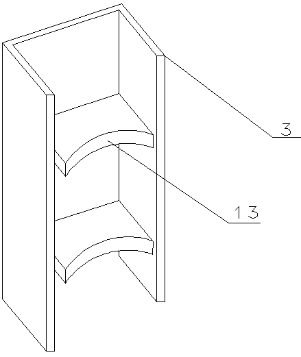
[0034] Fully automatic permanent magnet retractable device, such as Figure 4 , 5 , 6, and 7, the difference from the first embodiment is that the slideway 3 is two symmetrical semicircular tracks, the two sides of the slideway 15 are arc-shaped structures, and the parts of the arc-shaped structures on both sides of the slideway are connected with the semicircular tracks. The circular track matches, and the slide rail can slide up and down in the slideway. A circular hole 14 is provided at the lower end of the slide rail, and the free end of the spring 10 is fixed in the circular hole. One of the permanent magnet units is fixed on the bottom plate, the other permanent magnet unit is fixed on the front end surface of the slide rail, and the openings of the two permanent magnet units are opposite and arranged symmetrically. The working principle of this embodiment is exactly the same as that of Embodiment 1. The sliding rail moves up and down in the sliding rail under the acti...


PUM


Abstract

The invention discloses a full-automatic permanent magnetic telescopic device which comprises a bottom plate, slides, springs, sliding rails and a permanent magnetic device. The slides are fixedly arranged at the upper end of the bottom plate, the springs are fixed onto the bottom plate, the sliding rails are connected to free ends of the springs and can vertically move in the slides, the springsare arranged in the middles of the two symmetric slides, the permanent magnetic device comprises two permanent magnetic units, one permanent magnetic unit is fixedly arranged on the bottom plate or close to the lower portions of the slides of the bottom plate, the other permanent magnetic unit is fixed onto the sliding rails, the two permanent magnetic units are vertically symmetric, and the upperpermanent magnetic unit can vertically reciprocate relative to the lower permanent magnetic unit. Each permanent magnetic unit comprises a permanent magnet, an iron core, a coil and a permanent magnetic holder, wherein the coil is wound outside the iron core, the permanent magnetic holder is made of magnetic non-conducting materials, and the coil is connected with a power supply. The full-automatic permanent magnetic telescopic device is light in weight, small in size, wide in application range and stable in magnetism, can generate large permanent magnetic force due to addition of permanent magnetism, and can adapt to places with large and small thrust.

Description

technical field [0001] The invention relates to the technical field of permanent magnet power, in particular to a fully automatic permanent magnet stretching device. Background technique [0002] Telescopic device, which converts other forms of mechanical motion (such as cam mechanism to convert rotary motion into linear or other forms of motion) or force (such as electromagnetic push rod, using the working characteristics of electromagnet) into linear reciprocating motion, used to complete the target action. Currently used telescopic devices include a cam mechanism, a connecting rod mechanism, a hydraulic cylinder drive form or an electromagnetic push rod. The telescopic movement realized by the cam mechanism and the connecting rod mechanism is related to its own structural form and driving source. The structure is complex and the efficiency is low; the hydraulic cylinder is driven in the form of large volume, troublesome maintenance and pressure maintenance, and large po...

Claims


Application Information

Patent Timeline
Patent Type & Authority Applications(China)
IPC IPC(8): H02K33/00H02K33/02
CPCH02K33/00H02K33/02
Inventor 郝晓茹岳春晓汪成哲赵彦张小生
Owner HENAN POLYTECHNIC UNIV
Features
  • R&D
  • Intellectual Property
  • Life Sciences
  • Materials
  • Tech Scout
  • Unparalleled Data Quality
  • Higher Quality Content
  • 60% Fewer Hallucinations
Learn More