Geotechnical engineering safety monitoring system

A technology for safety monitoring and geotechnical engineering, applied in signal transmission systems, instruments, electrical components, etc., can solve problems such as slow response speed, lag in data utilization, and difficulty in on-site construction management, so as to improve accuracy and reduce monitoring blind spots. Effect

Inactive Publication Date: 2019-02-19
深圳众宝城贸易有限公司
View PDF0 Cites 1 Cited by
  • Summary
  • Abstract
  • Description
  • Claims
  • Application Information

AI Technical Summary

Problems solved by technology

The main problems existing in the existing monitoring methods are: 1. The installation and embedding process of sensors is complicated, the amount of sensor signal cables is large, and the cable layout is labor-intensive and time-consuming; A large amount buried in the concrete will reduce the structural strength and bring safety hazards. Once the cables are damaged during construction, the safety monitoring equipment will not work properly; 3. After the sensor is installed and buried, the signal cable will be led to MCU (data acquisition equipment), MCU is responsible for converting analog signals into digital signals, MCU is connected to PC to obtain data for analysis, and in the case of unattended, technicians are usually sent regularly to carry data transmission and storage equipment to the site for connection The MCU acquires data, so there are many signal transmission levels, data utilization lag, and slow response speed defects in data collection and utilization.
Although the method of obtaining data through CDMA / GPRS public wireless data network has been widely used in recent years, its reliability has also been questioned due to various uncertain factors in the long-distance data transmission link.

Method used


Image

  • Geotechnical engineering safety monitoring system
  • Geotechnical engineering safety monitoring system
  • Geotechnical engineering safety monitoring system

Examples


Embodiment Construction

[0014] The present invention is further described in conjunction with the following examples.

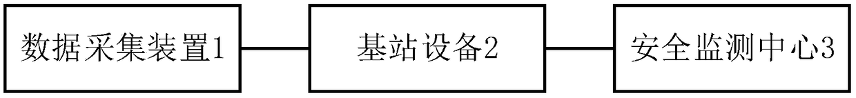
[0015] see figure 1 , a geotechnical engineering safety monitoring system, the geotechnical engineering safety monitoring system includes a data acquisition device 1, a base station device 2 and a safety monitoring center 3; the data acquisition device 1 includes a plurality of sensor nodes connected through a wireless sensor network, the sensor nodes It is used to collect geotechnical safety monitoring data and send it to the base station equipment 2. The base station equipment 2 aggregates the safety monitoring data sent by each sensor node and transmits it to the safety monitoring center 3.

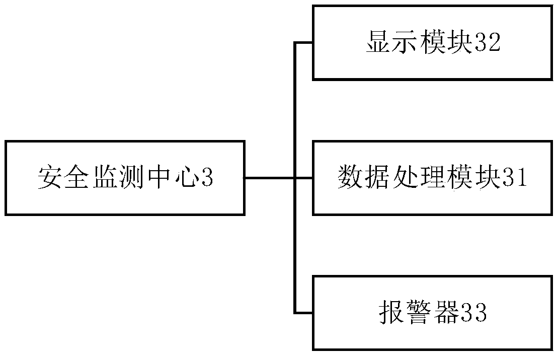
[0016] Preferably, the safety monitoring center 3 includes a data processing module 31 and a display module 32 , the data processing module 31 is used to compare the received safety monitoring data with a corresponding preset safety threshold, and output the comparison result to the display ...


PUM


Abstract

The invention discloses a geotechnical engineering safety monitoring system. The geotechnical engineering safety monitoring system comprises a data collection apparatus, a base station device and a safety monitoring center; and the data collection apparatus comprises a plurality of sensor nodes connected by a wireless sensor network, each sensor node is used for collecting geotechnical safety monitoring data and sending the same to the base station device, and the base station device aggregates the safety monitoring data sent by the sensor nodes and transmits the safety monitoring data to thesafety monitoring center. The geotechnical engineering safety monitoring system disclosed by the invention realizes the real-time collection, instant collection and instant utilization functions of the safety monitoring data, and solves the problems brought by onsite sensor installation and embedding and signal cable layout. According to the geotechnical engineering safety monitoring system disclosed by the invention, a plurality of sensors can be densely deployed according to the size of a safety monitoring project area without considering the cable deployment congestion degree, so that the monitoring dead zones are reduced; and a large amount of data are collected and processed through the wireless sensor network, thereby improving the monitoring accuracy.

Description

technical field [0001] The invention relates to the technical field of geotechnical structure monitoring, in particular to a geotechnical engineering safety monitoring system. Background technique [0002] At present, the safety monitoring of geotechnical engineering is mainly to evaluate the main structure of railways, highways, water conservancy and hydropower projects, slopes on both banks, foundations, soil displacement and settlement through instrument observation and patrol inspection, and judge the safety of the project , to provide management basis for supervisors, or to make risk warnings to prevent disasters and accidents. The main problems existing in the existing monitoring methods are: 1. The installation and embedding process of sensors is complicated, the amount of sensor signal cables is large, and the cable layout is labor-intensive and time-consuming; A large amount buried in the concrete will reduce the structural strength and bring safety hazards. Once t...

Claims


Application Information

Patent Timeline
Patent Type & Authority Applications(China)
IPC IPC(8): H04W4/38H04W40/10H04W40/32H04W84/18G08B21/18G08C17/02
CPCH04W4/38G08B21/18G08C17/02H04W40/10H04W40/32H04W84/18
Inventor 不公告发明人
Owner 深圳众宝城贸易有限公司
Why Eureka
Try Eureka