Planting shed

A technology of planting shed and rotating frame, applied in the field of planting shed, can solve the problems of low efficiency, poor effect, high working capacity requirements, etc., achieve uniform cooling, reduce vegetable diseases, and solve the effects of low ventilation efficiency

Active Publication Date: 2019-02-22
张向英
12 Cites 2 Cited by

AI-Extracted Technical Summary

Problems solved by technology

Ventilation and cooling is a relatively important link in the vegetable planting process, but the current vegetable planting sheds are generally ventilated by uncoveri...

Abstract

The invention discloses a planting shed. The planting shed includes a first bottom support pipe, a second bottom support pipe, a plurality of semi-circular elbow pipes, a water storage tank, a plurality of first rotating frames, a plurality of second rotating frames and a plurality of light transmission plates. The two ends of each semi-circular elbow pipe is communicated with a corresponding first installation hole and a corresponding second installation hole respectively, the water storage tank is embedded in soil, the first rotating frames and the second rotating frames are rectangular, theouter sides of the second rotating frames are sleeved with the first rotating frames, the light transmission plates are installed in the second rotating frames, the middles of a pair of side frames in parallel of each first rotating frame are hinged to the corresponding two adjacent semi-circular elbow pipes, and the middles of a pair of side frames in parallel of each second rotating frame are hinged to the other pair of side frames in parallel of the corresponding first rotating frame respectively. Hollow pipes are used for manufacturing the skeleton of the planting shed, the planting shedis cooled through circulating water, the temperature is uniform after cooling, and the ventilation angle and the ventilation opening degree are optimized through the first rotating frames and the second rotating frames which are arranged together.

Application Domain

Technology Topic

Image

  • Planting shed
  • Planting shed

Examples

  • Experimental program(1)

Example Embodiment

[0019] The present invention will be further described in detail below with reference to the accompanying drawings, so that those skilled in the art can implement it with reference to the text of the description.
[0020] It should be understood that terms such as "having", "including" and "including" used herein do not equate the presence or addition of one or more other elements or combinations thereof.
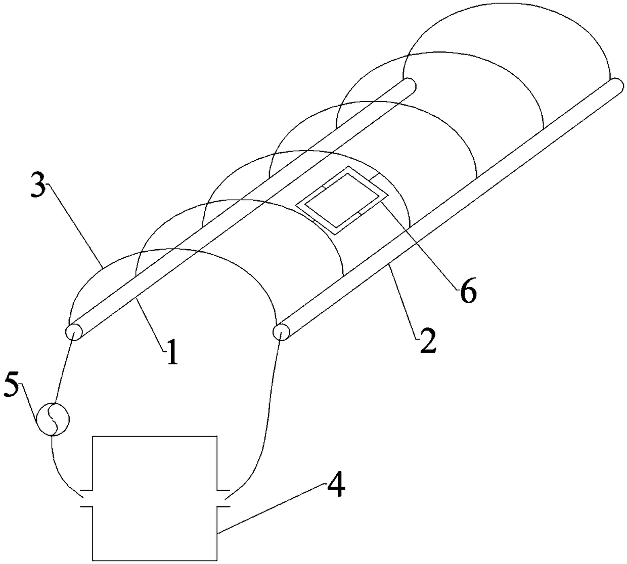
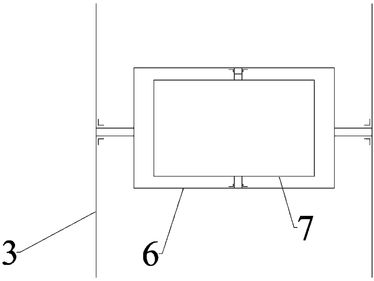
[0021] In a technical solution, such as figure 1 , 2 As shown, the planting shed includes:
[0022] The first bottom support tube 1 and the second bottom support tube 2, the first bottom support tube 1 and the second bottom support tube 2 are arranged in parallel and spaced apart, and the first bottom support tube 1 is provided with a plurality of The surface of the second bottom support tube 2 is provided with a plurality of second mounting holes at intervals, and the first mounting holes and the second mounting holes correspond one-to-one, the first One end of the bottom support pipe 1 forms a first water inlet, and one end of the second bottom support pipe 2 forms a first water outlet;
[0023] A plurality of semi-circular elbow pipes 3, two ends of each semi-circular elbow pipe 3 respectively communicate with the corresponding first mounting hole and the second mounting hole;
[0024] The water storage tank 4 is buried in the soil. The water storage tank 4 is formed with a second water inlet and a second water outlet. The second water outlet and the second water inlet are connected to the water outlet pipe and the water inlet pipe respectively. The first water inlet is in communication with the first water outlet, and the water outlet pipe is provided with a circulating water pump 5;
[0025] A plurality of first rotating frames 6, a plurality of second rotating frames 7 and a plurality of light-transmitting plates, the first rotating frame 6 and the second rotating frame 7 are both rectangular, and the first rotating frame 6 sets Set on the outside of the second rotating frame 7, the light-transmitting plate is installed in the second rotating frame 7, and the middle of a pair of parallel frames of the first rotating frame 6 are respectively connected with two adjacent semi-cylindrical elbows Hinged, the middle of a pair of parallel frames of the second rotating frame 7 are hinged to another pair of parallel frames of the first rotating frame 6, and the rotation axes of the first rotating frame 6 and the second rotating frame 7 Vertically, the first rotating frame 6 and the second rotating frame 7 are driven by a first motor and a second motor, respectively.
[0026] In the above technical solution, the first bottom support tube 1 and the second bottom support tube 2 constitute the load-bearing part of the planting shed, and the two ends of the multiple semicircular elbow tubes 3 are fixed to the first bottom support tube 1 and the second bottom support tube. The upper skeleton of the planting shed is formed between the tubes 2. The first bottom support pipe 1 and the second bottom support pipe 2 are respectively formed with a first water inlet and a first water outlet, and the water storage tank 4 supplies water to the first water inlet so that water flows in from the first bottom support pipe 1 through multiple The semi-circular elbow 3 enters the second bottom support tube 2 and flows out from the first water outlet into the water storage tank 4, so that the heat inside the planting shed can be taken out, and the circulating water uses the low temperature in the soil to cool down , Thereby continuously cooling the planting shed. Such as figure 2 As shown, the first rotating frame 6 is arranged between two adjacent semicircular elbows 3, preferably, arranged at a position close to the top of the planting shed. The first rotating frame 6 can be fixed on the outside of a pair of parallel frames. The rotating shaft is hinged with two adjacent semicircular elbows 3 through the first rotating shaft. The first rotating shaft is driven by the first motor. The second rotating frame 7 can fix the second rotating shaft on the outside of a pair of parallel frames. It is hinged with another pair of parallel frames of the first rotating frame 6, and the second rotating shaft is driven by a second motor. When the first rotating frame 6 and the second rotating frame 7 are in the initial position, the first rotating frame 6, the second rotating frame 7 and the light transmitting plate just close the planting shed. At this time, the first rotating shaft and the second rotating shaft are perpendicular , Making the rotation paths of the first rotating frame 6 and the second rotating frame 7 vertical. Preferably, the first rotation axis is parallel to the first bottom support tube 1. By rotating the first rotation frame 6, vents with various angles and openings can be formed in the direction perpendicular to the first bottom support tube 1. The rotating frame 6 can form vents with various angles and openings in the direction perpendicular to the first bottom support tube 1. By rotating the second rotating frame 7, various vents can be formed in a direction parallel to the first bottom support tube 1. The angle and opening of the vent, while rotating the first rotating frame 6 and the second rotating frame 7 can form other forms of openings to meet different situations. It can be seen that this technical solution uses the hollow first bottom support tube 1, the second bottom support tube 2, and the semicircular elbow 3 to make the skeleton of the planting shed. The temperature is lowered, and the temperature is lowered more uniformly, and by using multiple first rotating frames 6, the first rotating frame 6 and the second rotating frame 7 nested together, the ventilation angle and the amount of ventilation are adjusted in real time to solve the problem of ventilation in the prior art. The problems of low efficiency and poor ventilation have reduced vegetable diseases to a certain extent.
[0027] In another technical solution, in the planting shed, the multiple semicircular elbows 3 are covered with a shed film except for the area where the first rotating frame 6 is installed. Here, a plurality of semi-circular elbow pipes 3, the first bottom support tube 1, and the second bottom support tube 2 form a semi-cylindrical skeleton, which is covered with a shed film to form a planting shed, and is reserved for installing the first rotating frame 6 area.
[0028] In another technical solution, in the planting shed, a temperature sensor and a humidity sensor are arranged in a space enclosed by the shed film, and a wind direction detector is arranged outside the space enclosed by the shed film. Here, the intelligence of the present invention is improved. By detecting the internal temperature and humidity of the planting shed, and combining the wind direction, the ventilation angle and the ventilation opening are adjusted to provide a better humid temperature environment for vegetable planting.
[0029] In another technical solution, in the planting shed, the plurality of first rotating frames 6 are staggered. Here, the relative positions of all the first rotating frames 6 and the semicircular elbows 3 are made different, which reduces the dead angle of ventilation in the planting shed.
[0030] In another technical solution, the planting shed further includes a plurality of rainwater collecting funnels, the plurality of rainwater collecting funnels are all fixed on the semicircular elbow 3, the plurality of rainwater collecting funnels are all Connect with the water storage tank 4. Here, rainwater is used to circulate water, which reduces the cost of planting sheds to a certain extent.
[0031] In another technical solution, the planting shed further includes solar panels, and the solar panels are used to supply power to the circulating water pump 5, the first motor, and the second motor. Here, power is supplied by solar panels, which reduces the use cost of the planting shed to a certain extent and saves energy.
[0032] The number of equipment and processing scale described here are used to simplify the description of the present invention. The application, modification and change of the planting shed of the present invention are obvious to those skilled in the art.
[0033] Although the embodiments of the present invention have been disclosed above, they are not limited to the applications listed in the specification and embodiments. It can be applied to various fields suitable for the present invention. For those skilled in the art, it can be easily Therefore, without departing from the general concept defined by the claims and equivalent scope, the present invention is not limited to the specific details and the illustrations shown and described here.

PUM

no PUM

Description & Claims & Application Information

We can also present the details of the Description, Claims and Application information to help users get a comprehensive understanding of the technical details of the patent, such as background art, summary of invention, brief description of drawings, description of embodiments, and other original content. On the other hand, users can also determine the specific scope of protection of the technology through the list of claims; as well as understand the changes in the life cycle of the technology with the presentation of the patent timeline. Login to view more.

Similar technology patents

Control method of cooling device for quenching

Owner:LIUZHOU LONGXING DIE & MOLD TECH

Shelf assembly

Owner:QINGDAO HAIER REFRIGERATOR CO LTD +1

Steam waste heat recycling system for autoclaved aerated concrete blocks

ActiveCN114393683AUniform coolingEnsure uniform dispersionCeramic shaping apparatusProcess engineeringAutoclaved aerated concrete
Owner:SHANTOU XIJIA BUILDING MATERIALS

Classification and recommendation of technical efficacy words

Why Eureka
Try Eureka