Method and apparatus for effecting rapid thermal cycling of samples in microtiter plate size

a microtiter plate and sample technology, applied in biochemistry apparatus, electric heating furnaces, baking, etc., can solve the problems of slow heating/cooling process, difficult to interface the cycler with robots, and difficulty in pulling the sample holders (e.g., microtiter plates) out of the block at the end of the process, so as to achieve rapid heating and uniform heating and/or cooling of samples

Inactive Publication Date: 2002-09-05
INTEGRATED GENETIC DEVICES
View PDF0 Cites 9 Cited by
  • Summary
  • Abstract
  • Description
  • Claims
  • Application Information

AI Technical Summary

Benefits of technology

0008] According to one aspect of the present invention, there is provided a method of effecting rapid thermal cycling of samples, comprising: producing a high-velocity air flow through a channel defining a closed loop flow path; energizing an electrical heater within the closed loop flow path to heat the air flowing therethrough to a desired temperature; introducing a sample holder containing at least one sample into a section of the closed loop flow path for exposing the sample holder to the high-velocity heated air flowing therethrough for rapidly heating the sample; and rapidly cooling the sample to a desired temperature by de-energizing the electrical heater, and opening an air outlet from the closed loop flow path, while continuing to produce the high-velocity air flow through the channel.
0009] According to further features in the described preferred embodiment, the air flow produced through the section of the channel into which the sample holder is introduced is a laminar air flow, and the channel is of rectangular cross-section. These features aid in producing a uniform heating and / or cooling of the samples.

Problems solved by technology

In the case of thermal-block cyclers using Peltier elements, the large thermal mass of the block causes the heating / cooling process to be slow.
Another disadvantage of the block-cyclers is the difficulty in pulling the sample holders (e.g., microtiter plates) out of the block at the end of the process because of the deformation of the sample holders, usually plastic wells, caused by the temperature variations.
Such deformations make it difficult to interface the cycler with robots which are generally needed for high-throughput processing.
Thermal cyclers using water baths have also been used for this purpose, but the high thermal mass of the water also extends the time required for a complete heating / cooling cycle, such that a 30-cycle PCR process also takes a substantial period of time to complete.
Various types of thermal cyclers based on the circulation of air have been proposed, such as described for example in U.S Pat. Nos. 3,616,264, 4,420,679 and 5,455,175, but the previously known thermal cyclers of this type have not been found completely satisfactory for efficiently, rapidly and uniformly carrying out the PCR process, and / or do not allow standard sample holders of the rectangular matrix type, such as the microtiter plate, to be conveniently used.

Method used


Image

  • Method and apparatus for effecting rapid thermal cycling of samples in microtiter plate size
  • Method and apparatus for effecting rapid thermal cycling of samples in microtiter plate size
  • Method and apparatus for effecting rapid thermal cycling of samples in microtiter plate size

Examples


Embodiment Construction

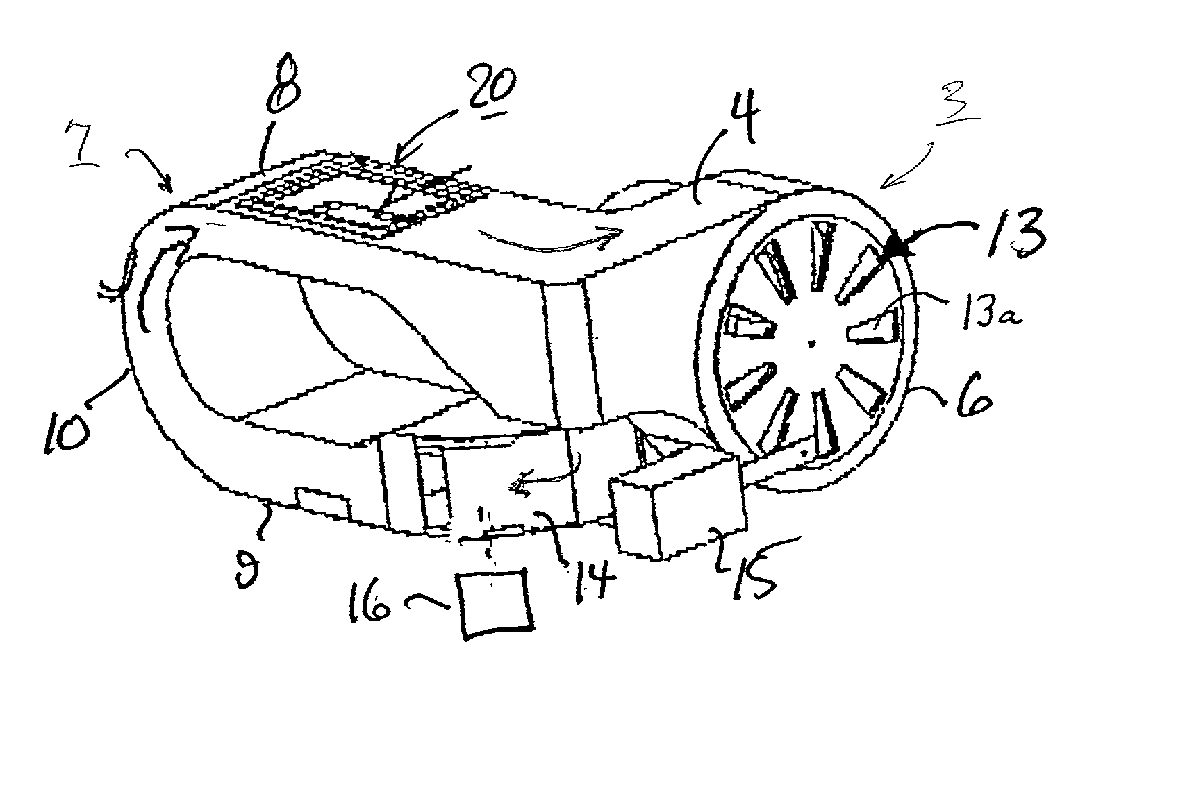
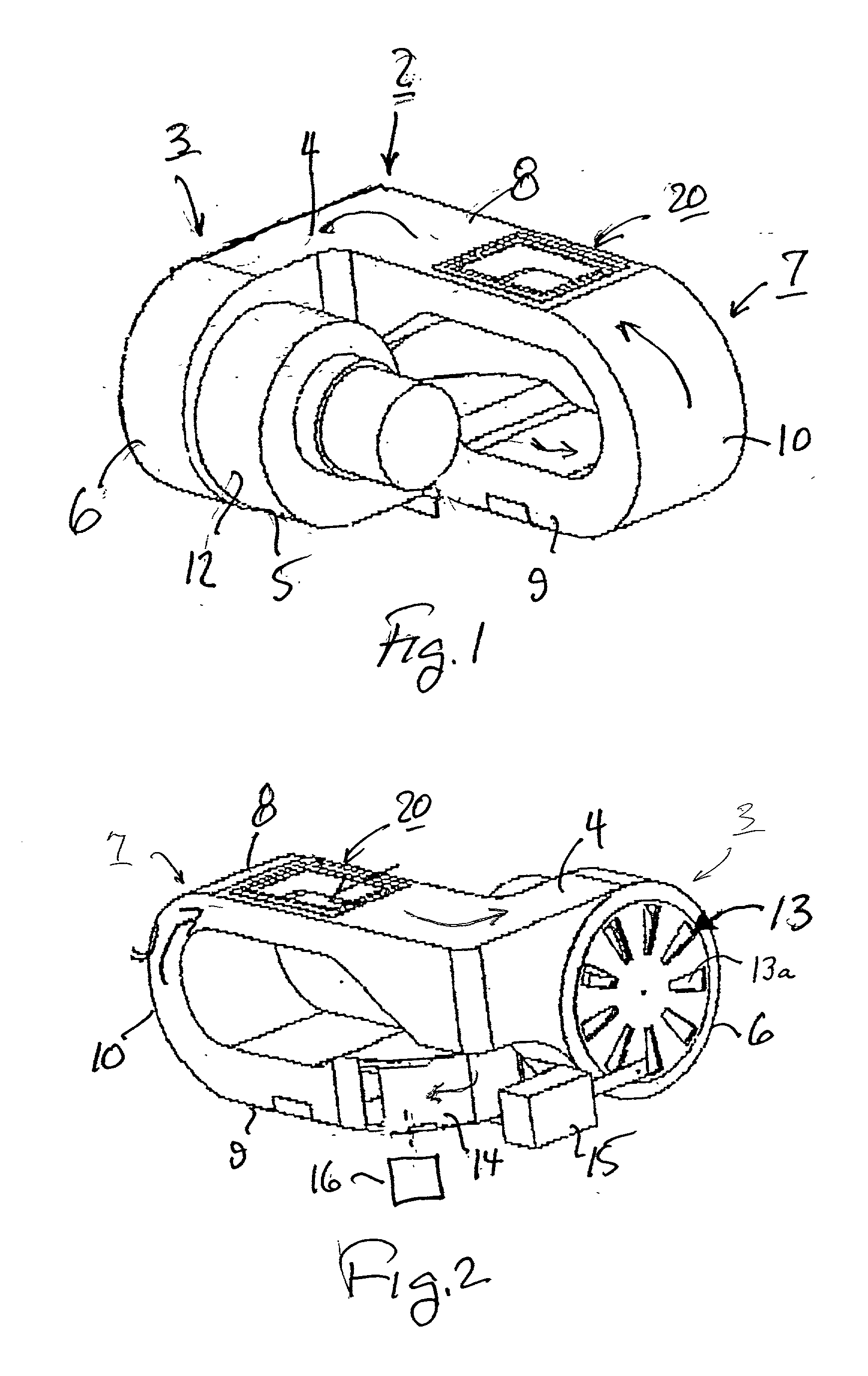
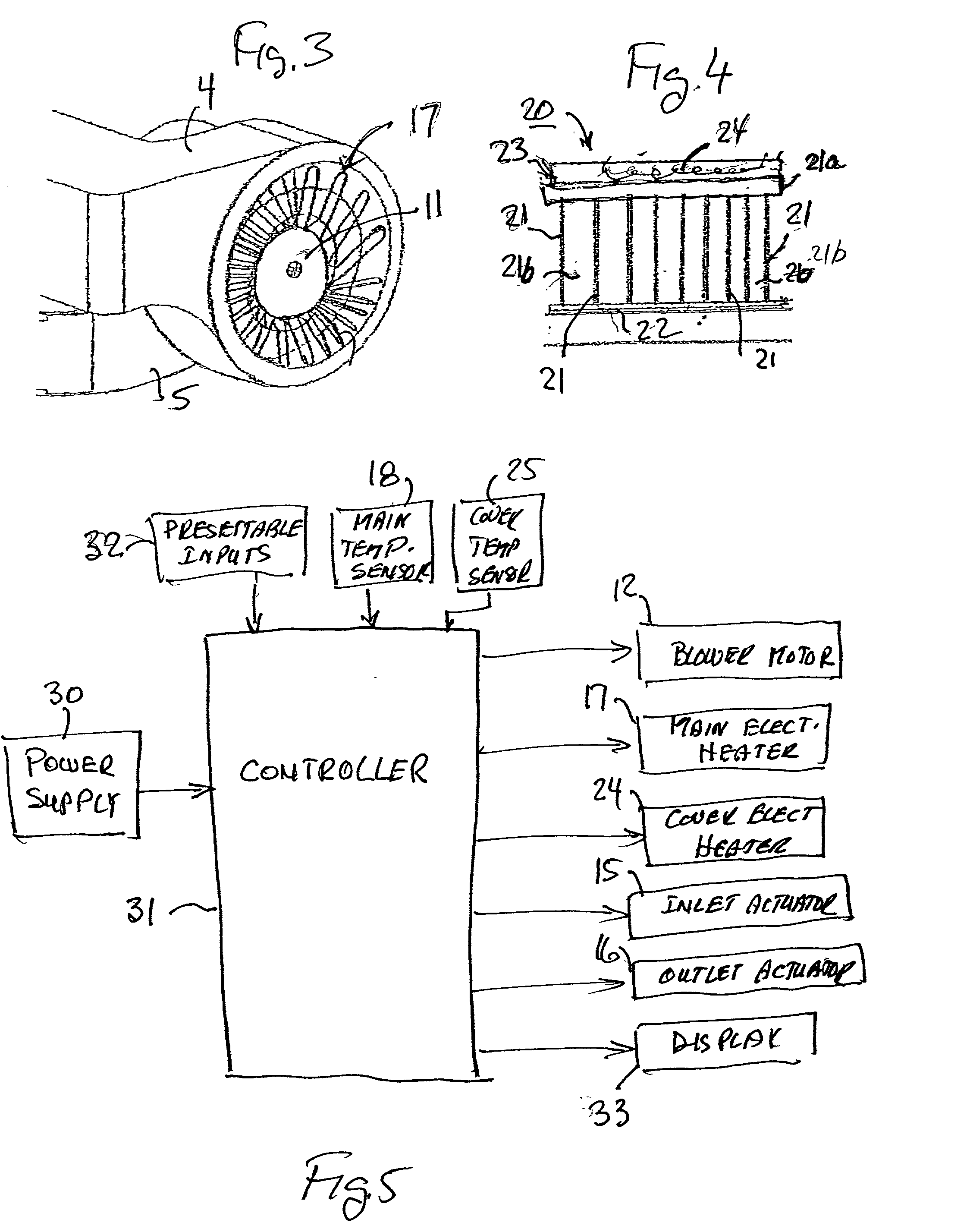
[0027] The thermal cycling apparatus illustrated in the drawings comprises a housing 2 defining a closed loop channel constituted of a first section, generally designated 3, including a first leg 4, and a second leg 5 parallel to leg 4 and joined to it by a U-shaped juncture 6. Housing 2 includes a second section, generally designated 7, constituted of a third leg 8, and a fourth leg 9 parallel to leg 8 and joined to it by a second U-shaped juncture 10. Legs 4 and 5 of housing section 3 are perpendicularly joined to legs 8 and 9 of housing section 7, such that the two housing sections 3 and 7 are joined to each other in an L-configuration.

[0028] All of the foregoing legs 4, 5, 8, 9, as well as their respective U-shaped junctures 6 and 10, are of a channel configuration such that when the two housing sections 3, 7 are joined to each other as described above, they define a continuous closed loop flow path 11 (FIG. 3) constituted of two U-shaped loops joined perpendicularly to each oth...


PUM

PropertyMeasurementUnit
air velocityaaaaaaaaaa
lengthaaaaaaaaaa
internal diameteraaaaaaaaaa

Abstract

A method and apparatus for effecting rapid thermal cycling of samples, by producing a high-velocity air flow through a closed loop flow path, and energizing an electrical heater within the closed loop flow path to heat the air flowing therethrough to a desired temperature. A sample holder is introduced into the closed loop flow path for exposing the sample holder to the high-velocity heated air flowing therethrough for rapidly heating the sample. The sample is rapidly cooled to a desired temperature by de-energizing the electrical heater, and opening an air outlet from the closed loop flow path, while continuing to produce the high-velocity air flow therethrough.

Description

[0001] The present application is a continuation-in-part of application Ser. No. 09 / 796,542, filed Mar. 2, 2001.FIELD AND BACKGROUND OF THE INVENTION[0002] The present invention relates to a method and apparatus for effecting rapid thermal cycling of samples. The invention is particularly useful in a process called "Polymerase Chain Reaction", or PCR, in a biological process called Cyclic DNA Amplification, and is therefore described below particularly with respect to this application, but it will be appreciated that the invention could advantageously be used in other applications involving the heating and / or cooling of samples.[0003] The PCR process involved in Cyclic DNA Amplification requires rapidly varying the temperature of a plurality of samples repeatedly through predetermined temperature cycles in a precisely controlled manner. Existing thermal cyclers can generally be divided into two main categories: (a) cyclers based on thermal blocks into which the samples are introduce...

Claims


Application Information

Patent Timeline
Patent Type & Authority Applications(United States)
IPC IPC(8): B01L7/00
CPCB01L7/52B01L7/54
Inventor TAL, MICHAELLIVNEH, JOSHUALIRAN, YORAM
Owner INTEGRATED GENETIC DEVICES
Why Eureka
Try Eureka