Radiating nozzle of 3D printer

A 3D printer and nozzle technology, applied in 3D object support structures, coating devices, additive manufacturing, etc., can solve problems such as uneven air velocity, printer nozzle vibration, printer nozzle clogging, etc., to ensure adhesion firmness, improve Heat dissipation efficiency, the effect of prolonging the time

Pending Publication Date: 2017-05-17
SICHUAN COLLEGE OF ARCHITECTURAL TECH
View PDF9 Cites 9 Cited by
  • Summary
  • Abstract
  • Description
  • Claims
  • Application Information

AI Technical Summary

Problems solved by technology

However, while the material is melting, the high temperature will also be transmitted to the nozzle cavity. If the temperature in the cavity reaches a certain temperature, the material will begin to soften and deform in the cavity. This will not only affect the final accuracy of the printed model, but may also lead to The nozzle of the printer is clogged, causing the printer to malfunction
At present, the commonly used method is to arrange a cooling fan outside the nozzle cavity to force the heat dissipation by accelerating the air flow, but this method can only blow to half of the nozzle cavity, and the air velocity is uneven, which is easy to cause the nozzle cavity to dissipate heat Uneven, there is still overheating inside the cavity, and it cannot completely effectively block the heat diffusion of the heating block
At the same time, the use of a single cooling fan will also bring certain vibrations to the printer nozzle, which will affect the quality of the final model.

Method used


Image

  • Radiating nozzle of 3D printer
  • Radiating nozzle of 3D printer
  • Radiating nozzle of 3D printer

Examples


Embodiment 1

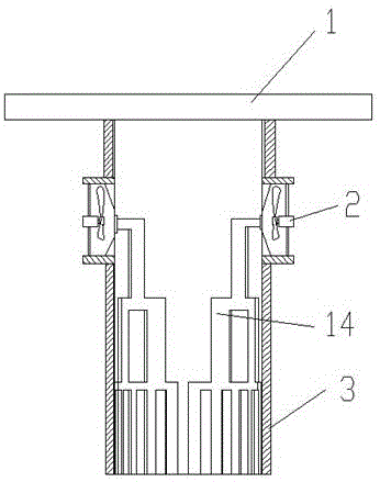
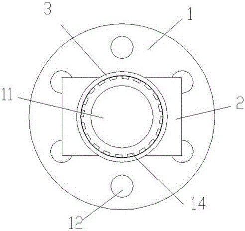
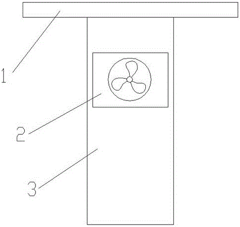
[0028] Such as Figure 1-5 As shown, a heat dissipation nozzle of a 3D printer of the present invention includes a spray head 1, an air blower 2 and a sleeve 3, the spray head 1 has a material spray channel 11, and the outside of the material spray channel 11 side wall is provided with a heat dissipation groove 14, The heat dissipation groove 14 diverges towards the outlet of the spraying channel 11; the air blower 2 is used to supply air to the heat dissipation groove 14, and the sleeve 3 is set on the spray head 1 and cooperates with the heat dissipation groove 14 to form a heat dissipation channel. The air outlet direction of the air outlet of the heat dissipation channel is the same as the spraying direction of the spray head 1 . The inner sidewall of the sleeve 3 covers and seals the notch of the cooling groove 14 . The cooling groove 14 has a branch structure, and there is a rectangular protrusion at the branch, and a local vortex can be formed when the air flows throug...

Embodiment 2

[0030] A heat dissipation nozzle of a 3D printer of the present invention comprises a spray head 1, an air blower 2 and a casing 3, the spray head 1 has a material spray channel 11, and the outer side of the material spray channel 11 side wall is provided with a heat dissipation groove 14, and the heat dissipation groove 14 diverges toward the outlet of the spraying channel 11; the air blower 2 is used to supply air to the heat sink 14, and the sleeve 3 is set on the spray head 1 and cooperates with the heat sink 14 to form a heat dissipation channel. The nozzle 1 includes a tubular portion and a connecting portion, the connecting portion is disc-shaped and located at one end of the tubular portion, the cooling groove 14 is located on the outer wall of the tubular portion, and the cooling groove 14 diverges away from the connecting portion. 3. Cooperate with the outside of the tubular part.

[0031] The outer wall of the tubular part has an air-gathering cavity 13, and the gas...


PUM


Abstract

The invention relates to a radiating nozzle of a 3D printer and belongs to the technical field of parts of 3D printing equipment. The radiating nozzle comprises a sprayer, an air supply apparatus and a sleeve, wherein a spraying channel is arranged in the sprayer; a radiating groove is formed in the outer side of the side wall of the spraying channel and radiates in the outlet direction of the spraying channel; the air supply apparatus is used for supplying air to the radiating groove; and the sleeve is arranged on the sprayer in a sleeving manner and is matched with the radiating groove to form a radiating channel. The structure can directly form the radiating channel on the surface of the nozzle to prolong the time that air flow passes through the nozzle and improve the radiating efficiency of the nozzle; as the divergent radiating channel is adopted to synchronously cool the periphery of the spraying channel more uniformly, the radiating efficiency is improved, and blockage caused by excessive reduction of local temperature is avoided. The air-out direction of an air outlet of the radiating channel is the same as the spraying direction of the sprayer; the air at the back of a cooling sprayer is used for preheating, softening and dedusting a to-be-sprayed part so as to ensure adhesion firmness of materials sprayed one after another.

Description

technical field [0001] The invention relates to a heat dissipation nozzle of a 3D printer, belonging to the technical field of 3D printing equipment components. Background technique [0002] 3D printing technology is a type of rapid prototyping manufacturing technology that has developed rapidly in recent years. It is based on computer technology, through software layered discrete and numerical control molding systems, using high-energy laser beams, hot-melt nozzles, etc. to process metals, ceramic powders, plastics, etc. The manufacturing method of layer-by-layer accumulation and bonding of materials such as cell tissue and cell tissue. At present, the most widely used in the field of 3D printing technology is called fusion deposition molding, that is, FDM method, which mainly transports thermoplastic polymer wires to high-temperature printing heads, melts the wires and continuously extrudes molten polymers, and The three-piece shape is built by layering layer by layer und...

Claims


Application Information

Patent Timeline
Patent Type & Authority Applications(China)
IPC IPC(8): B29C64/112B29C64/209B29C64/30B29C35/16B33Y30/00
CPCB29C35/16B33Y30/00B29C2035/1666
Inventor 武鹏飞包宗贤颜凌云陈秀梅
Owner SICHUAN COLLEGE OF ARCHITECTURAL TECH
Why Eureka
Try Eureka