Core clamping device

A clamping device and core technology, which is applied in the field of casting tooling, can solve the problems of complex operation and heavy core workload, and achieve the effects of high versatility, guaranteed clamping strength, and cost savings

Active Publication Date: 2019-02-22
KOCEL EQUIP
View PDF5 Cites 3 Cited by
  • Summary
  • Abstract
  • Description
  • Claims
  • Application Information

AI Technical Summary

Problems solved by technology

[0003] The invention overcomes the disadvantages of the existing technology that clamping the core by means of the upper and lower plates requires a larg

Method used


Image

  • Core clamping device
  • Core clamping device
  • Core clamping device

Examples


Example Embodiment

[0018] In order to enable those skilled in the art to better understand the technical solutions of the present invention, the present invention will be further described in detail below in conjunction with specific examples. Please note that the embodiments described below are exemplary only for explaining the present invention, and should not be construed as limiting the present invention. If no specific technique or condition is indicated in the examples, it shall be carried out according to the technique or condition described in the literature in this field or according to the product specification.

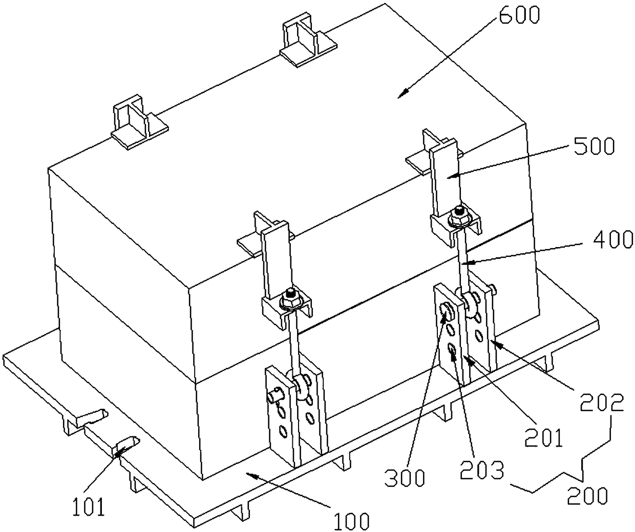
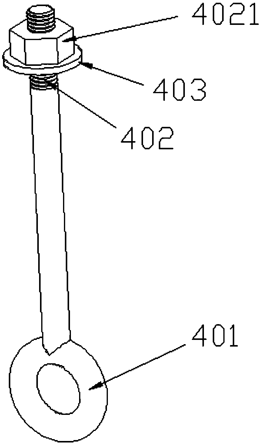
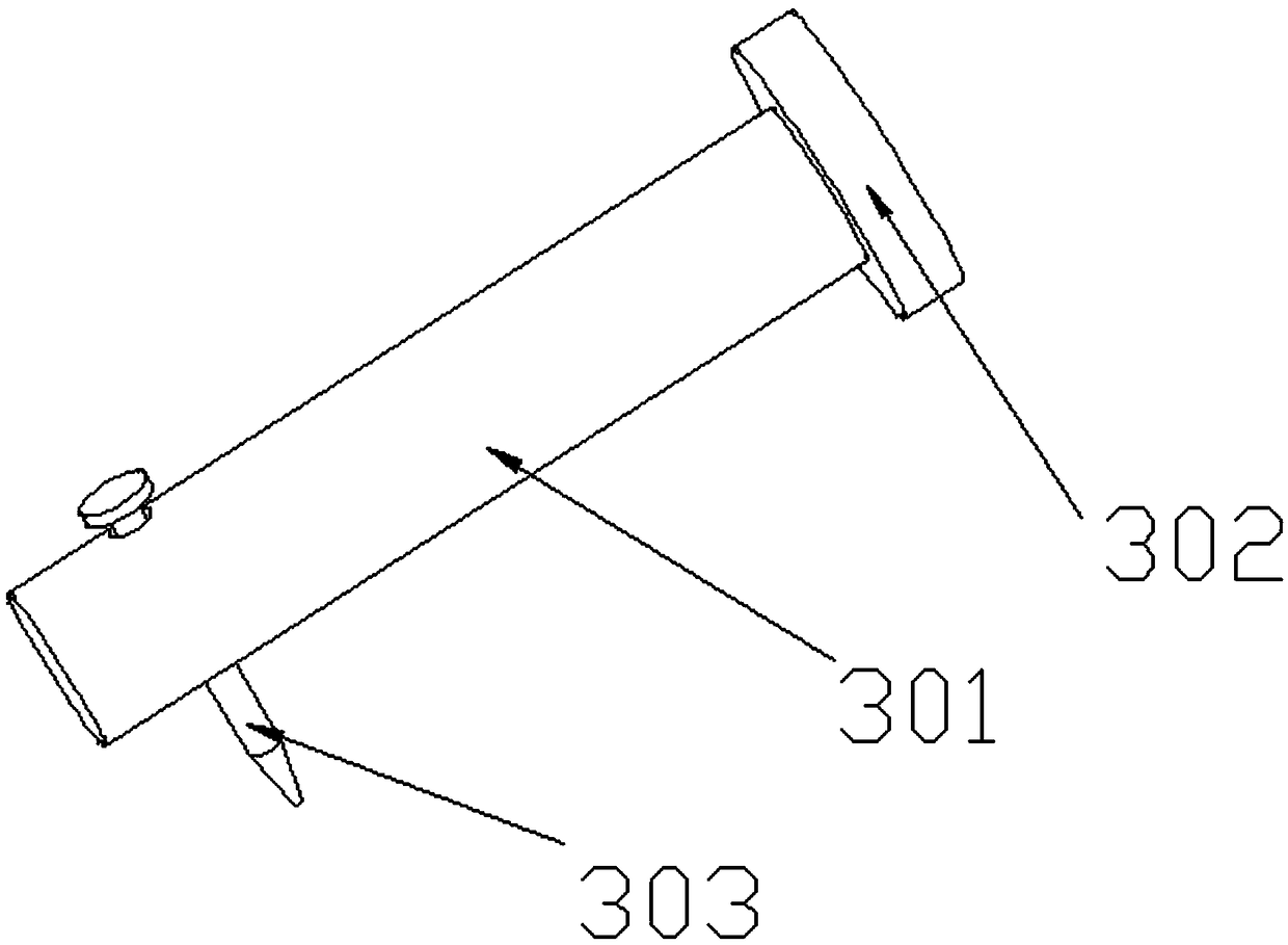
[0019] like Figure 1 to Figure 4 As shown, a core clamping device includes: a template 100, a fixing mechanism 200, a clamping mechanism 300, a connecting rod 400 and a clamping plate 500; the template 100 is a flat plate with a horizontal top surface, which is used for placing Core 600; the fixing mechanism 200 includes a first fixing plate 201 and a second fixing plate 20...


PUM


Abstract

The invention relates to a core clamping device. The core clamping device comprises templates, fixing mechanisms, clamping mechanisms, connecting rods and clamping plates; the templates are flat plates with horizontal top surfaces; each clamping mechanism comprises a clamping column, a baffle and a baffle rod; the clamping columns are rotationally arranged in clamping connection holes; circular rings are arranged at one ends of the connecting rods; the circular rings are arranged on the clamping columns in a sleeve mode; each clamping plate comprises a first clamping plate, a second clamping plate and a third clamping plate; clamping grooves matched with one ends, far away from the circular rings, of the connecting rods are formed in the third clamping plates; and the connecting rods are fixedly connected to the clamping grooves so that the fixing mechanisms are connected to the clamping plates. The core clamping device can meet the clamping connection of the cores with different heights and different sizes, the universal degree is high, and various types of clamping tools in the prior art can be avoided; and the clamping connection strength of the core is ensured, and the clampingcomplexity is reduced.

Description

technical field [0001] The invention relates to a casting tool, in particular to a core clamping device for a core assembly process. Background technique [0002] Due to the small ratio of sand to iron in boxless molding, no need to use sandboxes, easy sand shakeout, and reduced box-fitting steps, more and more castings with small single weight and large batches are produced by boxless molding technology. Generally, the boxless shape adopts the core assembly process. Although the core assembly process has significant advantages, the conventional clamping structure realizes the clamping through the connection between the upper and lower templates and the fastening screw, which involves the transfer of the template, screw assembly and fastening operations, and the workload is large and the operation is relatively complicated. Complexity and difficult site transfer have caused many disadvantages to mass production. Contents of the invention [0003] The invention overcomes ...

Claims


Application Information

Patent Timeline
IPC IPC(8): B22C9/10
CPCB22C9/108
Inventor 柴润川马林马秉平
Owner KOCEL EQUIP
Why Eureka
Try Eureka