Water jet scalpel deflection mechanism

A technology of deflection mechanism and water jet, which is applied in metal processing and other directions, can solve the problems of complex adjustment, blocking, limited rotation angle, etc., and achieve the effect of simple deflection adjustment

Pending Publication Date: 2019-02-22
FOSHAN YONGSHENGDA MACHINERY
View PDF0 Cites 0 Cited by
  • Summary
  • Abstract
  • Description
  • Claims
  • Application Information

AI Technical Summary

Problems solved by technology

This kind of deflection technology, although the cutting point does not change after the offset, it needs the power vertical rotation mechanism to rotate at a certain angle to compensate for the X-axis and Y-axis of the water jet in the horizontal direction caused by the rotation of the power rotation member. The deviation, because the deflection of the water jet and the rotation of the power vertical rotation mechanism are all arc rotations, and the angle of rotation of the power rotation member is different from the angle of the vertical Z axis of the water jet, resulting in maintaining the horizontal direction When the X-axis and Y-axis above are unchanged, it is very complicated to obtain the required adjustment of the angle of the water jet that deviates from the vertical Z-axis
In addition, the angle at which the water jet deviates from the vertical Z axis is much smaller than the rotation angle of the power rotating member. For example, if the power rotating member rotates 90 degrees, the angle at which the water jet deviates from the vertical Z axis is only 60 degrees. When the power rotating member rotates, the angle of the power rotating member The fixed seat is rotated downward, and it will be blocked by the workbench or the workpiece on the processing table after the rotation exceeds a certain angle. Therefore, the angle of rotation is limited, which leads to the limitation of the angle of the waterjet from the vertical Z axis, and it cannot be used for large angles. Cut off the Z axis,

Method used


Image

  • Water jet scalpel deflection mechanism
  • Water jet scalpel deflection mechanism

Examples


Embodiment Construction

[0010] Now in conjunction with accompanying drawing and embodiment the present invention is described in further detail:

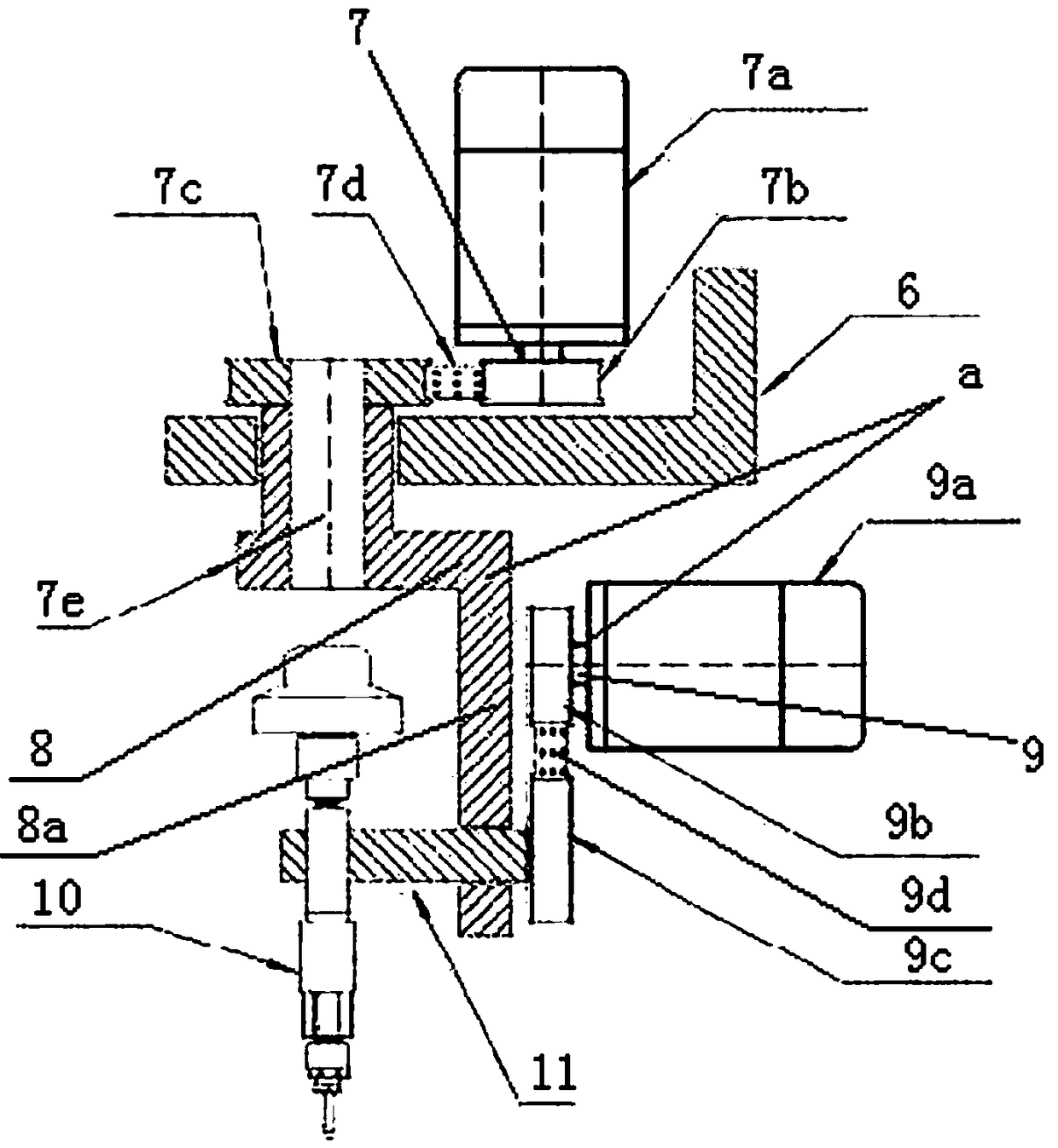
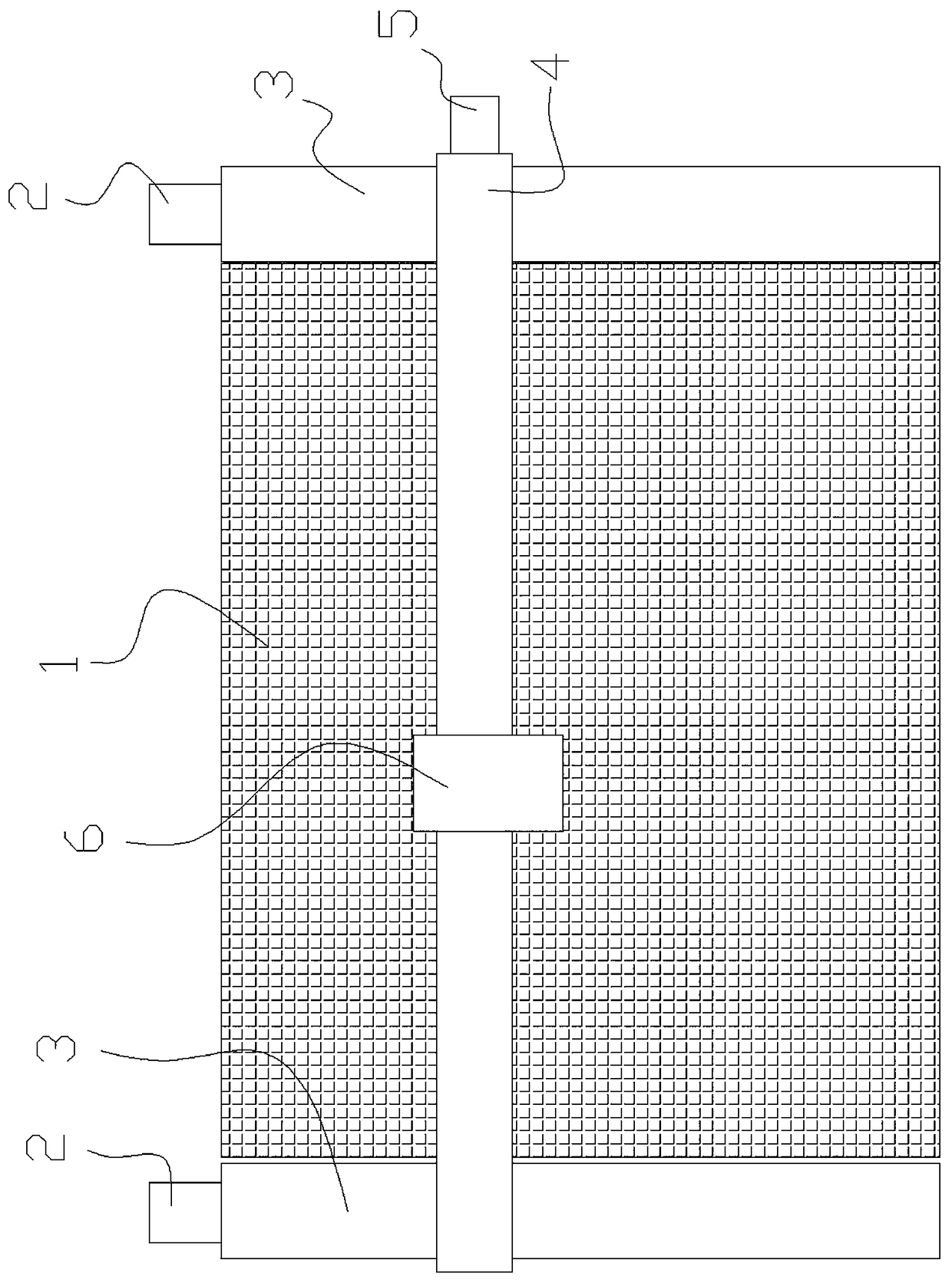
[0011] Such as figure 1 , 2 As shown, the present invention includes a crossbeam 4 arranged on the processing table 1 driven by the power 2 to move forward and backward along the guide rail 3, a moving seat 6 arranged on the crossbeam 4 to move left and right driven by the power 5, and a moving seat 6 arranged on the moving seat 6. The power vertical rotation mechanism 7 (comprising the motor 7a that is arranged on the mobile seat 6, the driving pulley 7b driven by the motor 7a, the driven pulley 7c, the belt 7d that is connected on the driving pulley 7b and the driven pulley 7c, driven by the driven pulley 7c The vertically rotating shaft 7e), the deflection mechanism a driven by the shaft 7e of the power vertical rotation mechanism 7, its special feature is that the deflection mechanism a includes an inverted L-shaped rotating seat 8, a vertical seat a...


PUM


Abstract

The invention relates to a water jet scalpel deflection mechanism which comprises a cross beam drive by power so as to move front and back along a guide rail, a moving seat arranged on the cross beamand driven by power so as to move left and right, a power perpendicular rotating mechanism arranged on the moving seat, and a deflection mechanism driven by the power perpendicular rotating mechanismso as to rotate. The water jet scalpel deflection mechanism is characterized in that the deflection mechanism comprises an inverted L-shaped rotating seat, a power rotation component arranged on a perpendicular seat of the inverted L-shaped rotating seat, and a water jet scalpel cutting head driven by the power rotation component; the water jet scalpel cutting head is fixed onto a fixed seat of the power rotation component; and the rotation axis of the power rotation component is perpendicular to the perpendicular seat of the inverted L-shaped rotating seat. Compared with the prior art, the water jet scalpel deflection mechanism provided by the invention has the advantages of simplicity in adjusting water jet scalpel deflection, and capability of cutting in a way of large-angle deviating from the Z axis.

Description

Technical field: [0001] The invention relates to a water jet cutting technology. Background technique: [0002] Such as figure 2 As shown, the existing technology of deflecting the water jet to cut the workpiece on a bevel is to connect a 45-degree inclined seat to the rotating shaft of the power vertical rotation mechanism, and then set the power rotation on the 45-degree inclined plane perpendicular to the inclined seat. component, the water jet is vertically connected to the fixed seat of the power rotating component, so that no matter how the rotation angle of the power rotating component changes, the water jet deviates from the vertical Z axis by a certain angle, because its rotation axis coincides with the cutting point of the water jet, Therefore, the position of the cutting point will not change. This kind of deflection technology, although the cutting point does not change after the offset, it needs the power vertical rotation mechanism to rotate at a certain angl...

Claims


Application Information

Patent Timeline
IPC IPC(8): B23D79/00B26F3/00
CPCB23D79/00B26F3/00
Inventor 刘永钦
Owner FOSHAN YONGSHENGDA MACHINERY
Why Eureka
Try Eureka