High-efficiency press-fitting gear bushing tool

A press-fitting and gear technology, which is applied in the field of gear processing, can solve the problems of reducing product quality, bushing extrusion burrs, and reducing production and processing efficiency, so as to improve processing efficiency and avoid pressure deviation.

Pending Publication Date: 2019-02-22
TIANJIN TAIWEI GEAR
View PDF0 Cites 0 Cited by
  • Summary
  • Abstract
  • Description
  • Claims
  • Application Information

AI Technical Summary

Problems solved by technology

[0002] At present, when press-fitting the bushes on both sides of the gear, a large flat-type press-fitting tool is used. During the press-fitting process, it is easy to produce pressure deviation, crookedness, uneven pressure, and the bushing is extruded and burrs, which reduces the product quality. quality, but also reduces the efficiency of production and processing

Method used


Image

  • High-efficiency press-fitting gear bushing tool
  • High-efficiency press-fitting gear bushing tool
  • High-efficiency press-fitting gear bushing tool

Examples


Embodiment 1

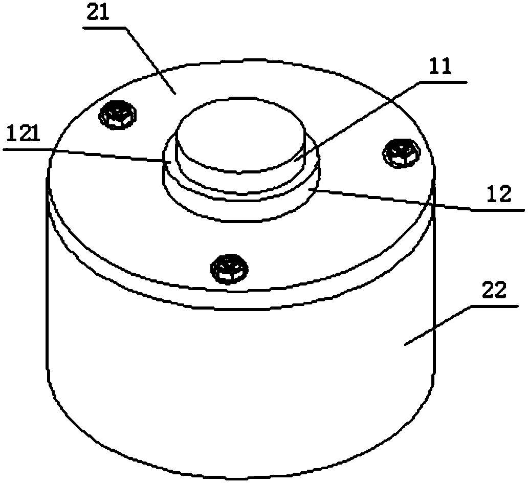
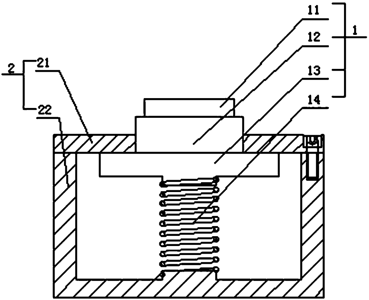
[0029] Such as Figure 1-2 As shown, a high-efficiency press-fit gear bushing tooling includes a floating boss 1 and a loading platform 2; the floating boss 1 includes a small boss 11, a large boss 12, a limit plate 13 and a floating guide mechanism; the small boss Platform 11 is a cylindrical structure, and the lower end of small boss 11 extends downwards to form a large cylindrical boss 12. The diameter of big boss 12 is greater than the diameter of small boss 11. Meanwhile, small boss 11 and big boss The intersection of the platform 12 forms an annular step surface 121; the lower end of the large boss 12 is fixed with a limit plate 13, and a floating member 14 is provided at the lower end of the limit plate 13; the loading platform 2 includes a flat plate 21 and a base 22. The flat plate 21 is detachably installed on the upper end of the base 22, and a cavity is provided in the base 22;

[0030] There is a circular through hole in the center of the plate 21, the large boss...

Embodiment 2

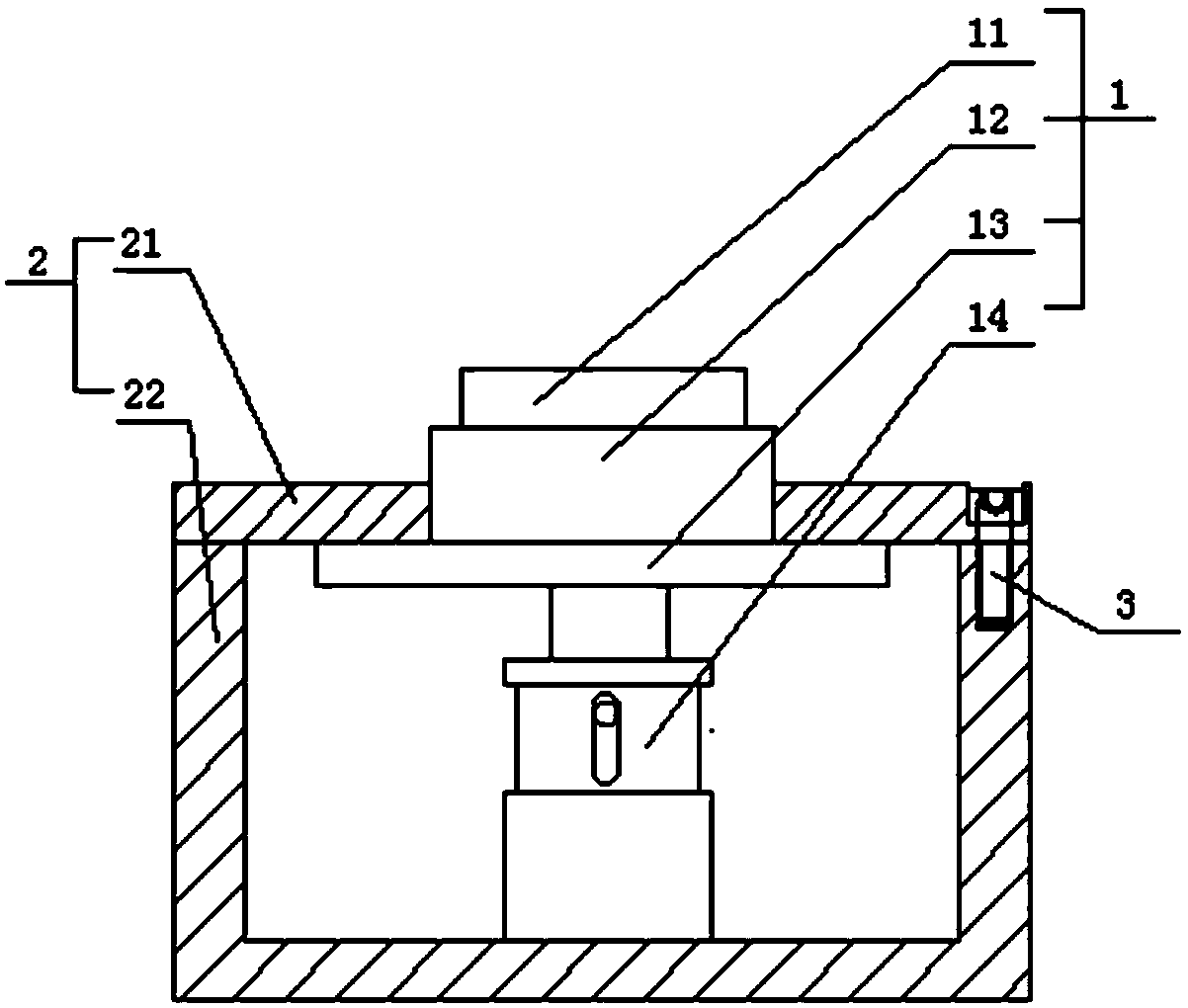
[0034] Such as figure 1 and Figure 3-5 As shown, a high-efficiency press-fit gear bushing tooling includes a floating boss 1 and a loading platform 2; the floating boss 1 includes a small boss 11, a large boss 12, a limit plate 13 and a floating guide mechanism; the small boss Platform 11 is a cylindrical structure, and the lower end of small boss 11 extends downwards to form a large cylindrical boss 12. The diameter of big boss 12 is greater than the diameter of small boss 11. Meanwhile, small boss 11 and big boss The intersection of the platform 12 forms an annular step surface 121; the lower end of the large boss 12 is fixed with a limit plate 13, and a floating member 14 is provided at the lower end of the limit plate 13; the loading platform 2 includes a flat plate 21 and a base 22. The flat plate 21 is detachably installed on the upper end of the base 22, and a cavity is provided in the base 22;

[0035] There is a circular through hole in the center of the plate 21, ...


PUM


Abstract

The invention belongs to the technical field of gear processing, and particularly relates to a high-efficiency press-fitting gear bushing tool which comprises a floating boss and a loading platform. The floating boss comprises a small boss, a big boss, a limiting plate and a floating guiding mechanism; the limiting plate is fixedly connected to the lower end of the big boss; a floating component is arranged at the lower end of the limiting plate; the locating platform comprises a flat plate and a base; the flat plate is detachably arranged at the upper end of the base; a cavity is arranged inthe base; a circular through hole is formed in the center of the flat plate; the big boss penetrates through the through hole; the limiting plate and the floating component are located in a cavity ofthe base; the floating component comprises an elastic piece; the elastic piece is directly or indirectly connected with the limiting plate; and along with the deformation of the elastic piece, the limiting plate can move up and down. According to the high-efficiency press-fitting gear bushing tool provided by the invention, the occurrence of the phenomenon that a bushing is pressed askew can be avoided, the product quality is improved, bushings on two sides can be conveniently press-fitted at one time, and the processing efficiency is improved.

Description

technical field [0001] The invention belongs to the technical field of gear processing, and in particular relates to a high-efficiency press-fit gear bush tooling. Background technique [0002] At present, when press-fitting the bushes on both sides of the gear, a large flat-type press-fitting tool is used. During the press-fitting process, it is easy to produce pressure deviation, crookedness, uneven pressure, and the bushing is extruded and burrs, which reduces the product quality. Quality, but also reduces the efficiency of production and processing. Contents of the invention [0003] In view of this, the present invention aims to provide a high-efficiency press-fit gear bushing tool, which can avoid the phenomenon of bush pressing and other phenomena, improve product quality, facilitate one-time press-fitting of both-side bushes, and improve processing efficiency. [0004] In order to achieve the above object, technical solution of the present invention is achieved in...

Claims


Application Information

Patent Timeline
IPC IPC(8): B25B27/02
CPCB25B27/02
Inventor 李俊杰何伟孟岩马杰赵涛宋嘉伟
Owner TIANJIN TAIWEI GEAR
Why Eureka
Try Eureka