

Rotor manufactruing method and rotor manufacturing device
A manufacturing method and technology for a manufacturing device, which are applied in the field of rotor manufacturing devices, can solve problems such as deviation in the axial position of a laminated iron core, deviation in the relative positional relationship of a rotating shaft, etc., and achieve the effect of preventing deviation from occurring.
- Summary
- Abstract
- Description
- Claims
- Application Information
AI Technical Summary
Problems solved by technology
Method used
Image

Examples
no. 1 approach
[0048] (Structure of the rotor)
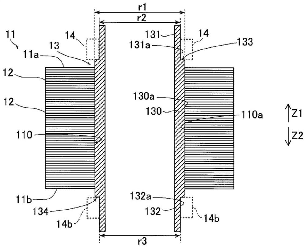
[0049] refer to Figure 1 to Figure 14 The structure of the rotor 10 of the first embodiment will be described.
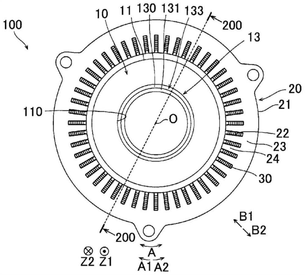
[0050] In the specification of this application, "axial direction" refers to the direction along the rotation axis (reference sign O) (Z1 direction, Z2 direction) of the rotor 10 (refer to figure 1 ). In addition, "circumferential direction" refers to the circumferential direction (A direction, A1 direction, A2 direction) of the rotor core 11 . In addition, "radially inward" means a direction (B1 direction) toward the center of the rotor core 11 . In addition, "radially outward" means the direction (B2 direction) toward the outer side of the rotor core 11. As shown in FIG.
[0051] Such as figure 1As shown, the rotating electric machine 100 includes a rotor 10 and a stator 20 . The stator 20 includes an annular stator core 21 . A plurality of slots 22 are provided in the stator core 21 . Segment conductors 30 are arranged i...
no. 2 approach
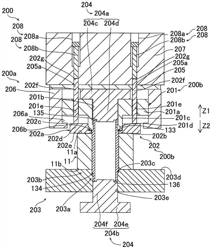
[0107] Next, refer to figure 2 ,as well as Figure 15 ~ Figure 23 The method of manufacturing the rotor 10 and the manufacturing apparatus 300 of the rotor 10 according to the second embodiment will be described. In the method of manufacturing the rotor 10 and the manufacturing apparatus 300 of the rotor 10 according to the second embodiment, unlike the above-described first embodiment in which the hydraulically driven hydraulic cylinder 208 is used, an air cylinder 308 with variable elasticity is used. In addition, the same structure as the said 1st Embodiment is attached|subjected and shown the same code|symbol as 1st Embodiment, and description is abbreviate|omitted.
[0108] (Structure of rotor manufacturing equipment)
[0109] Such as Figure 15 As shown, the manufacturing apparatus 300 of the rotor 10 includes a die 300 a for hydroforming. The die 300a for hydroforming has a die pressing portion 200b. The manufacturing apparatus 300 ( 300 a , 200 b ) of the rotor 1...
PUM
 Abstract
Description
Claims
Application Information