Hot melting and butt joint equipment of plastic pipeline

A technology for hot-melt butt joint and plastic pipe, applied in the field of pipe joint, can solve the problems of affecting the pipe precision, destroying the flatness, destroying the shape of the pipe, etc., so as to avoid deviation, ensure the clamping accuracy and ensure the stability.

Inactive Publication Date: 2019-02-22
黄力华
View PDF3 Cites 15 Cited by
  • Summary
  • Abstract
  • Description
  • Claims
  • Application Information

AI Technical Summary

Problems solved by technology

[0003] The existing pipe hot-melt butt joint equipment basically uses heating on the outside of the pipe to cause its hot-melt deformation, and then the two pipes are bonded together, and then the protrusions and residues at the joint are processed. The hot-melt butt joint of the pipe will not only damage the pipe The shape of the outer side will also deform the inner side of the pipe and destroy its flatness. The deformation at the inner seam of the pipe will affect the use effect of the pipe to a certain extent; the upper and lower parts are basically used to fix the pipe firmly. The arc-shaped plate that fits the outer ratio of the pipe is fastened by spiral closure. In the non-working state, the upper and lower arc-shaped plates are completely separated, and then installed during work. This is often disassembled. It will be very troublesome, and the split part is easy to lose. When the interchangeability between the two is not good, it will also affect the accuracy of fixing the pipe, which will bring some trouble to the docking work.

Method used


Image

  • Hot melting and butt joint equipment of plastic pipeline
  • Hot melting and butt joint equipment of plastic pipeline
  • Hot melting and butt joint equipment of plastic pipeline

Examples


Embodiment Construction

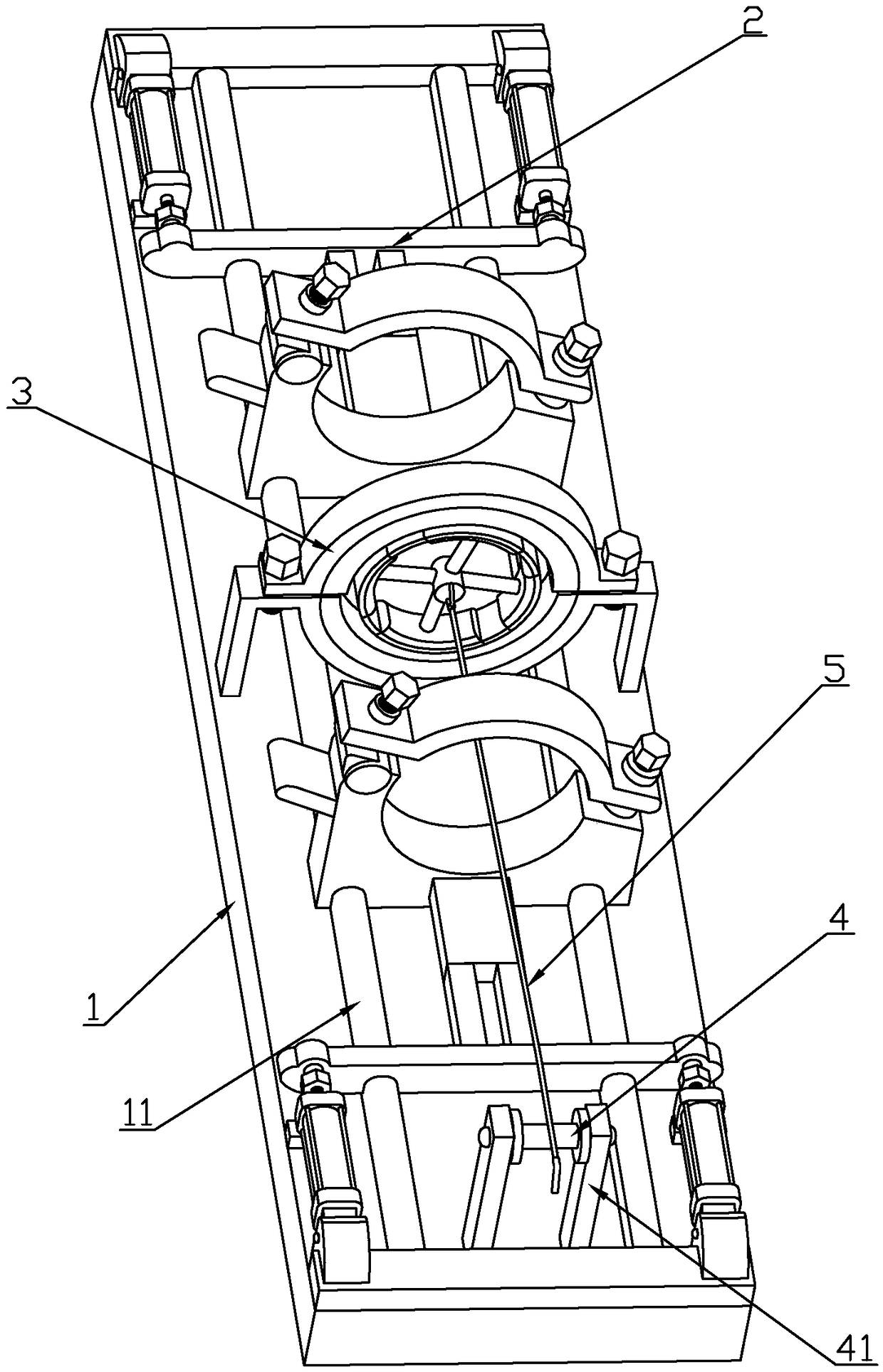
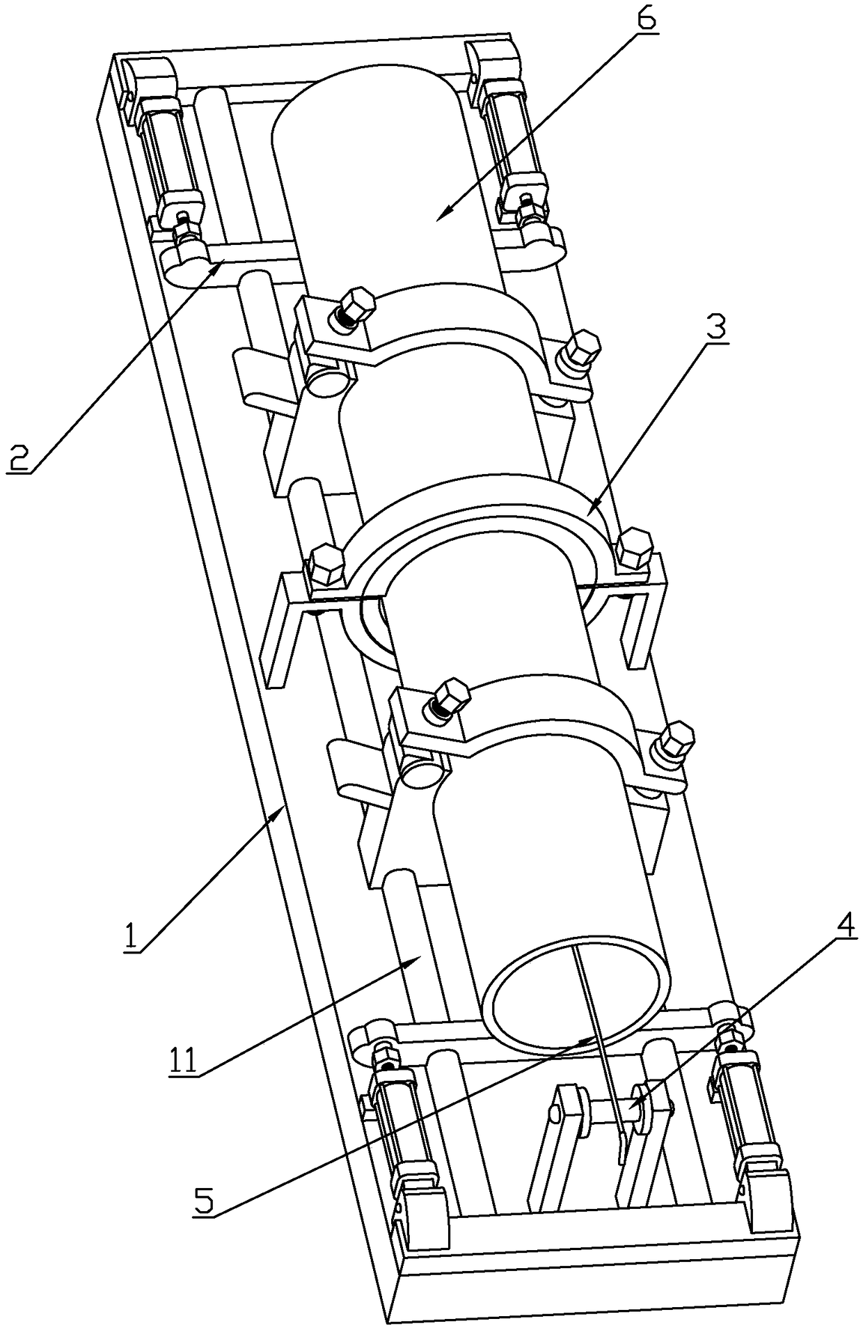
[0024] For the convenience of those skilled in the art to understand, the following in conjunction with the attached Figure 1-6 , to further specifically describe the technical solution of the present invention.

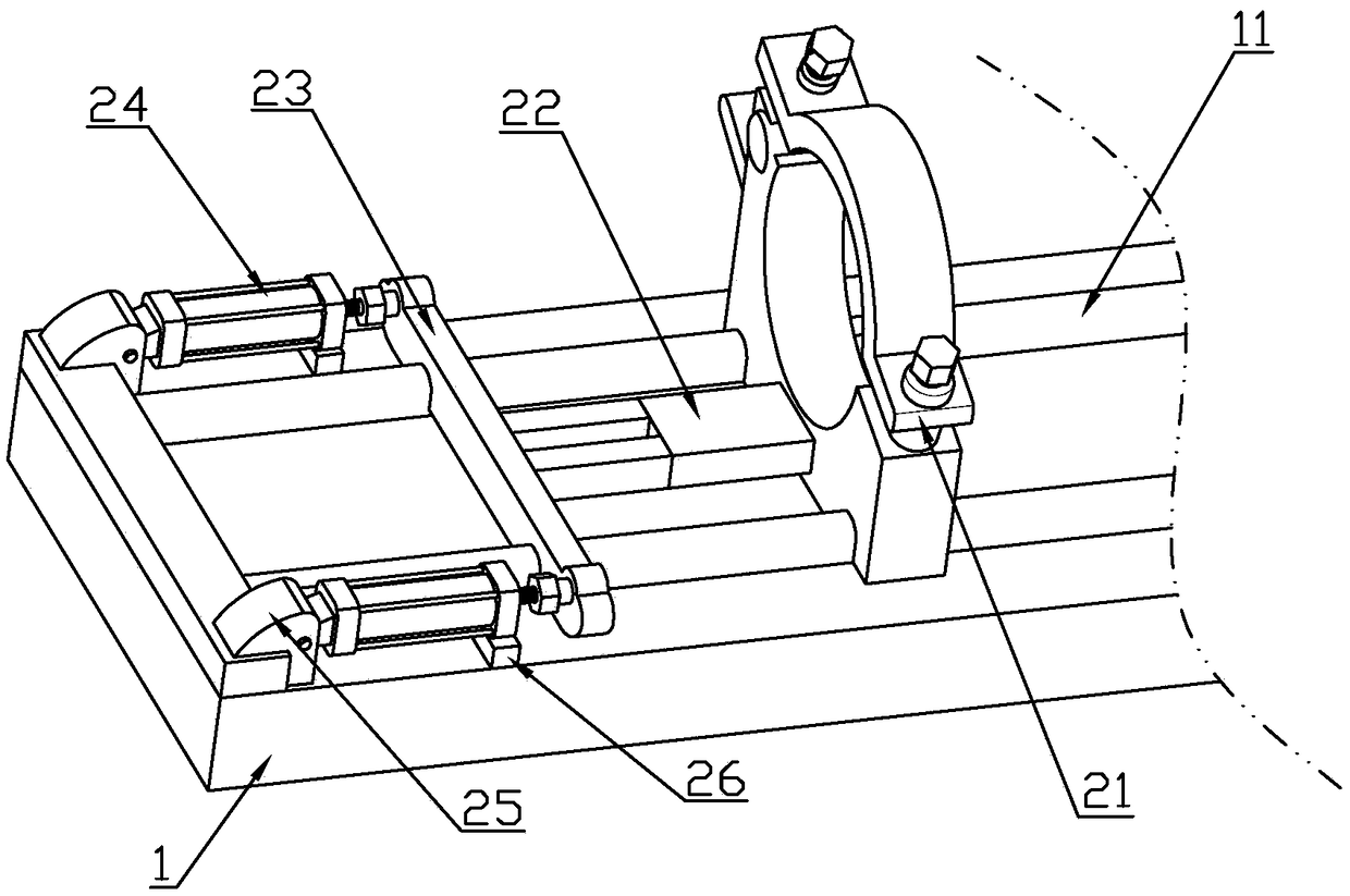
[0025] A plastic pipe hot-melt docking equipment, including a base 1, a push mechanism 2, a docking mechanism 3, and a traction rope 5, the base 1 is provided with two slide rails 11, and the middle part of the top side of the base 1 is provided with a docking mechanism 3 , the two sides of the docking mechanism 3 are respectively provided with a push mechanism 2, the push mechanism 2 is slidably socketed on the outside of the slide rail 11, and the two push mechanisms 2 respectively clamp the two pipes that need to be connected, and then they are close to each other, and the The joints of the pipes that need to be butted are placed inside the docking mechanism 3, and the butt joint is completed by the docking mechanism 3. The push mechanism 2 moves along the slide ...


PUM


Abstract

The invention discloses hot melting and butt joint equipment of a plastic pipeline. The equipment comprises a base, pushing mechanisms, a butt joint mechanism, and a traction rope; the base is provided with two slide rails; the middle of the top side of the base is provided with the butt joint mechanism, the two sides of the butt joint mechanism are each provided with one pushing mechanism, the pushing mechanisms are connected to the outer sides of the sliding rails in sliding and sleeving modes respectively; each pushing mechanism comprises a fixing support, the fixing support is mainly composed of a fixing base, a pressing cover and a retaining shoulder, the fixing base is arranged on one side of the base, and the two sides of the bottom end of the fixing base are slidably connected withtwo sliding rails respectively; and the butt joint mechanism comprises a lining assembly, the inner lining assembly is mainly composed of an inner heating ring, a connecting shaft, connecting rods, and arc plates, wherein the lining assembly is arranged on the inner side of a pipeline joint, the plurality of connecting rods are uniformly arranged on the outer side wall of the connecting shaft, and one end of each connecting rod is connected with one arc plate. The equipment is simple in structure, and the accuracy of pipeline clamping and the flatness of the joint of the inner side wall of the pipeline can be guaranteed.

Description

technical field [0001] The invention belongs to the technical field of pipe butt jointing, in particular to a plastic pipe hot-melt butt joint equipment. Background technique [0002] At present, when using plastic pipes, hot-melt welding is usually used when the length of the pipe is not enough. For some plastic pipes, it is necessary to connect a sleeve at the joint and then perform hot-melt welding. When the pipe diameter is large, it is necessary to stabilize the pipe. Generally, movable brackets are also used for fixing. [0003] The existing pipe hot-melt butt joint equipment basically uses heating on the outside of the pipe to cause its hot-melt deformation, and then the two pipes are bonded together, and then the protrusions and residues at the joint are processed. The hot-melt butt joint of the pipe will not only damage the pipe The shape of the outer side will also deform the inner side of the pipe and destroy its flatness. The deformation at the inner seam of the...

Claims


Application Information

Patent Timeline
Patent Type & Authority Applications(China)
IPC IPC(8): B29C65/18
CPCB29C65/18B29C66/522
Inventor 黄力华
Owner 黄力华
Why Eureka
Try Eureka