Clamp structure arranged on linear cutting machine

A wire cutting machine and wire cutting technology, applied in the field of tooling and fixtures, can solve the problems of low degree of versatility, seldom seen, and high precision requirements for LCD TV backplanes, and achieve the goal of helping production, reducing work intensity, and shortening clamping effect of time

Inactive Publication Date: 2014-05-14
金牌模具(常熟)有限公司
View PDF9 Cites 3 Cited by
  • Summary
  • Abstract
  • Description
  • Claims
  • Application Information

AI Technical Summary

Problems solved by technology

In addition, because the tooling fixture has the exclusive characteristics for the processing of a certain workpiece or product, the degree of versatility is extremely low, and it is often designed and manufactured by the manufacturer of the workpiece (or product) in a tailor-made manner.
It is precisely based on this factor that due to the special shape and high precision requirements of the punch used for punching the LCD TV backplane, there is no corresponding technical inspiration in the current published patents and non-patent literature

Method used


Image

  • Clamp structure arranged on linear cutting machine

Examples


Embodiment Construction

[0018] In order to enable the examiners of the patent office, especially the public, to understand the technical essence and beneficial effects of the present invention more clearly, the applicant will describe in detail the following in the form of examples, but none of the descriptions to the examples is an explanation of the solutions of the present invention. Any equivalent transformation made according to the concept of the present invention which is merely formal but not substantive shall be regarded as the scope of the technical solution of the present invention.

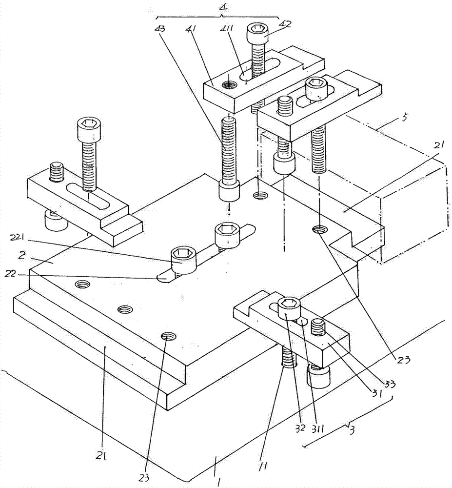
[0019] See figure 1 , a wire-cutting operation platform 1 belonging to the structure system of wire-cutting machine is given. A fixture plate 2 belonging to the structural system of the fixture structure of the present invention is given. The fixture plate 2 can be adjusted (also called movable) and set on the wire cutting operation platform 1. The two ends of the fixture plate 2 are figure 1 The left end an...


PUM


Abstract

The invention relates to a clamp structure arranged on a linear cutting machine, and belongs to the technical field of tool clamps. The linear cutting machine comprises a linear cutting operation platform, the clamp structure comprises a clamp plate, clamp plate limiting mechanisms and a workpiece limiting mechanism, wherein the clamp plate is arranged on the linear cutting operation platform, and the two ends of the clamp plate respectively extends to form a workpiece bracket; the pair of clamp plate limiting mechanism is connected with the linear cutting operation platform at the edge portions corresponding to the two sides in the length direction of the clamp plate respectively; the workpiece limiting mechanism is arranged on the clamp plate and corresponds to the upside of the workpiece brackets in the state of rising to the sky. The clamp structure is simple wholly, and not only facilitates manufacturing, but also is beneficial for facilitating operation; when a workpiece is clamped, it is only required that the workpiece is placed on the workpiece brackets, and the workpiece limiting mechanism is operated, so that the time for clamping the workpiece is shortened substantially, and the working efficiency of the linear cutting machine is improved; due to the fact that the clamp structure clamps the workpiece conveniently, rapidly and efficiently, operation intensity of an operator can be reduced substantially.

Description

technical field [0001] The invention belongs to the technical field of fixtures, and in particular relates to a fixture structure arranged on a wire cutting machine for clamping workpieces to be processed by wire cutting. Background technique [0002] In the field of metal parts processing and forming technology, various tools are required. Taking the stamping process of LCD TV backplane (material is metal) as an example, it is necessary to use various special punches, which are usually processed by wire cutting. and the clamping requirements are very strict, because if the clamping precision of the workpiece to be processed by wire cutting is low (that is, the error is large), it will affect the quality of the workpiece after wire cutting, such as the aforementioned punch, and even cause scrap. Therefore, in order to ensure the clamping accuracy of the workpiece as much as possible, the clamping time spent by the operator is relatively lengthy, which affects the wire cutti...

Claims


Application Information

Patent Timeline
Patent Type & Authority Applications(China)
IPC IPC(8): B23H11/00B23H7/02
Inventor 沈建刚沈钧
Owner 金牌模具(常熟)有限公司
Why Eureka
Try Eureka