
Method and apparatus for nano-capillary/micro electrospray for use in liquid chromatography-mass spectrometry

a micro-electrospray and liquid chromatography technology, applied in the field of liquid chromatography and mass spectrometry systems and the analysis of chemical samples, can solve the problems of small spray droplets, low ion transfer efficiency and sensitivity loss, and fine formation, and achieve the effect of easy alignmen

Active Publication Date: 2012-07-24
BRUKER SCI LLC +1
View PDF13 Cites 37 Cited by
  • Summary
  • Abstract
  • Description
  • Claims
  • Application Information

AI Technical Summary

Benefits of technology

[0015]Unlike NSI technology, the present invention allows the practitioner to easily attach the spray assembly to the MS. There is no need for microscopes, cameras or X,Y,Z positioning adjustment. Rather the spray assembly is simply attached to the MS inlet with a vacuum seal and is ready to perform its function within the MS. The present invention reduces set-up time and increases the speed in which mass spectrometry can be carried out versus NSI-MS. The present invention provides stable spray and uniform performance across a wide dynamic flow rate range (0.1-100+ ul / min).
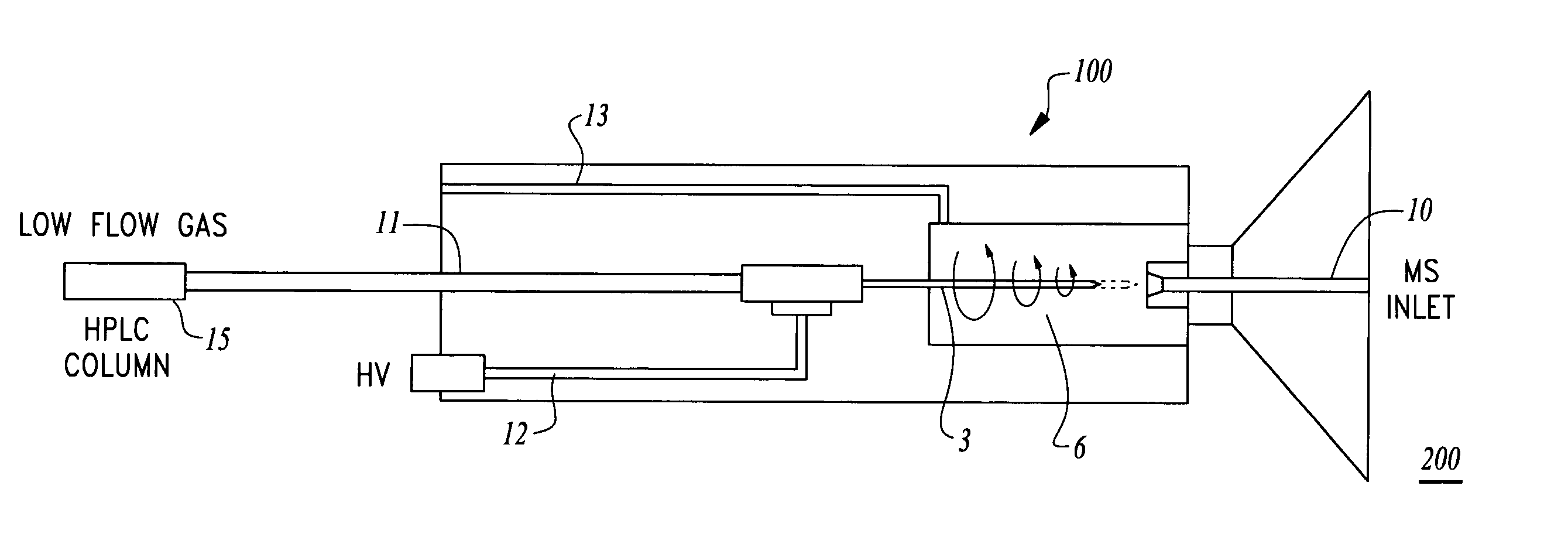
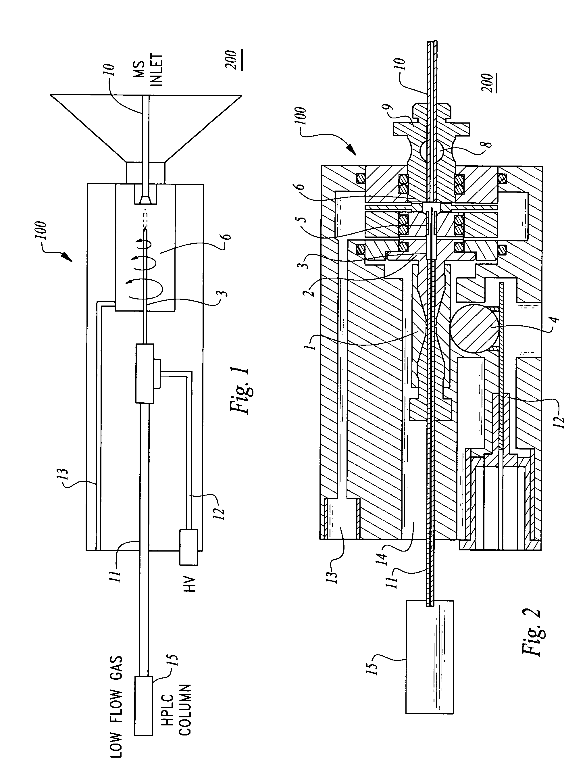
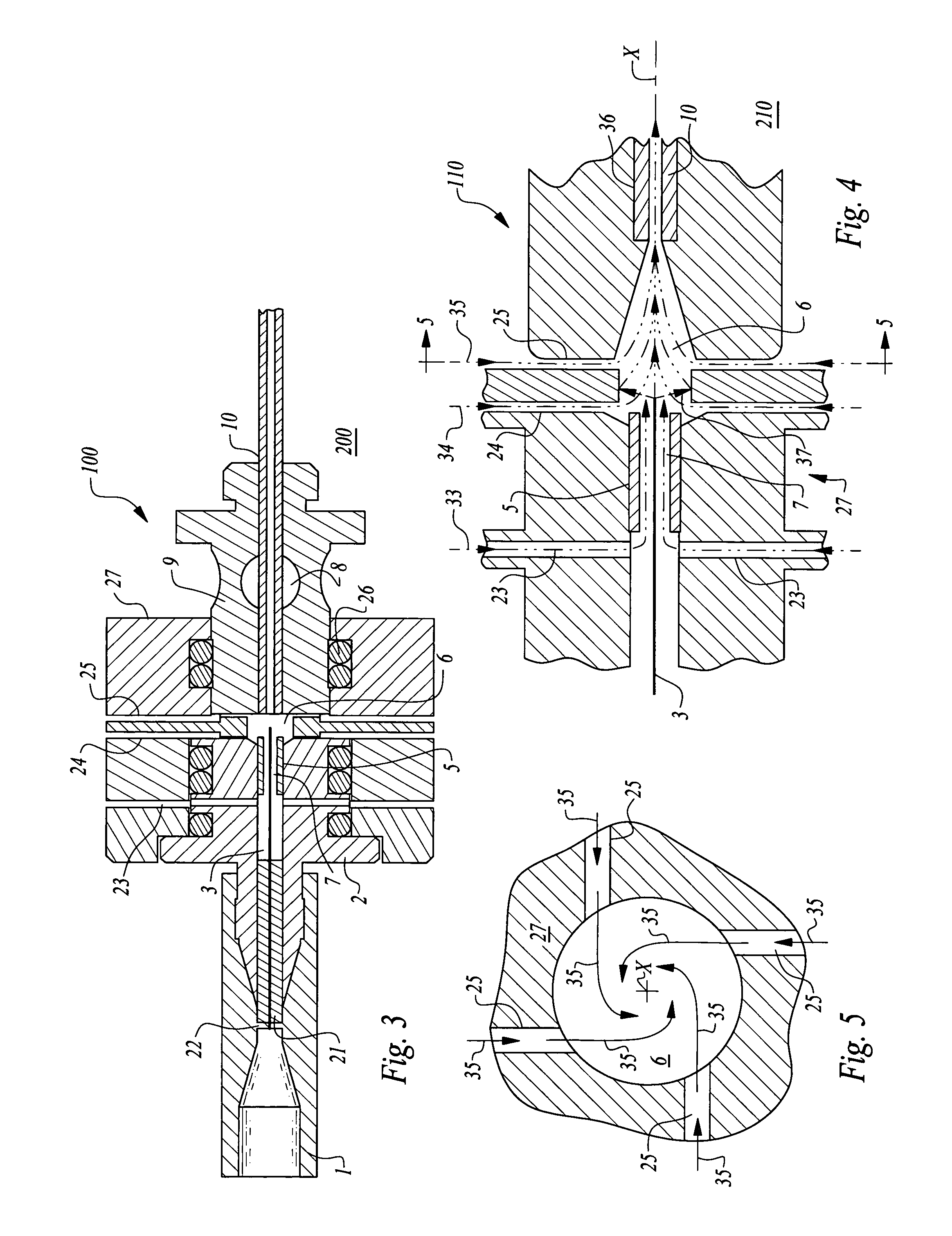
[0016]Coaxial gas flow is preferably introduced around the spray needle through an annular space between the spray needle and outer tube at high velocity, typically generated by the vacuum inlet of the MS. A second gas flow is preferably introduced at the spray needle outlet to focus the spray inward and a third gas flow is introduced in a centrifugal fashion to provide funnel-shaped swirling gas flow to help desolvate and focus the ions into the MS. The device of the present invention is preferably sealed by at least one O-ring to generate vacuum assisted gas flow and prevent loss of sample ions into the atmosphere. Unlike previous electrospray technology where the spray and drying gases are open to the atmosphere, the present invention uses the vacuum from MS to guide the flow of ions and gases in the sealed spray chamber into the MS and prevent loss of sample ions to the atmosphere.
[0018]Accordingly, a primary object of the present invention is to provide an ion injection spray device which can effectively convert samples such as those discharged from a liquid chromatograph (LC) into ions before passage into a mass spectrometer (MS).
[0021]Another object of the present invention is to provide an ion injection spray device which is easy to align with an inlet to a MS or other subatmospheric pressure mass analyzer.
[0022]Another object of the present invention is to provide an ion injection spray device which utilizes centrifugal flow of a gas adjacent an outlet of a spray needle to assist in keeping ions to be mass analyzed along a central axis flow path.

Problems solved by technology

This results in the formation of fine, charged droplets of solution containing the analyte molecules.
Although the gas assists in the formation of the spray and makes the operation of the electrospray ionization (ESI) easier and more robust, the excess gas dilutes the sample ions, resulting in lower ion transfer efficiency and a loss of sensitivity.
NSI utilizes very low liquid flows and a very narrow spray tip outlet placed very close to the MS inlet, which results in the formation of very small spray droplets which can be desolvated without gas assistance.
Since no gas is used in NSI, high ion transfer efficiency can be achieved, but at a cost of ease of use and robustness relative to pneumatic assisted electrospray.
NSI spray tips are generally made by pulling and cutting fused silica tubing to make the very small ID / OD tips required for stable spray at nanoliter per minute flow rates, but these tips are difficult to reproduce, fragile to handle and easy to clog.
Because of these limitations, NSI can be difficult to set up and maintain, making it poorly suited for analyses requiring robust operation.
Since NSI is generally limited to flow rates below 1 μl / min, samples must be separated using nanoLC which has its own share of problems and limitations.
NanoLC columns (<150 um ID) have limited sample capacity, require specialized sample injection protocols to load large sample volumes and lack the robustness of larger LC columns.
Finally, the low flow rates used in nanoLC / NSI-MS typically result in longer sample analysis time, making this technique poorly suited to high throughput applications like biomarker validation and pharmaceutical development.
Several attempts have been made to develop commercially viable microspray ionization (MSI) sources in an effort to overcome the limitations imposed by NSI, but these MSI sources have not been very well accepted.
Although these MSI sources, which are basically miniaturized versions of pneumatic assisted ESI, do offer increased stability and work at higher LC flow rates versus NSI, the added gas flow still results in a lower ion transfer efficiency and a unacceptable loss in sensitivity for most researchers.

Method used


Image

  • Method and apparatus for nano-capillary/micro electrospray for use in liquid chromatography-mass spectrometry
  • Method and apparatus for nano-capillary/micro electrospray for use in liquid chromatography-mass spectrometry
  • Method and apparatus for nano-capillary/micro electrospray for use in liquid chromatography-mass spectrometry

Examples


Embodiment Construction

[0033]As required, detailed illustrative embodiments of the present invention are disclosed herein. However, techniques, systems and operating structures in accordance with the present invention may be embodied in a wide variety of sizes, shapes, forms and modes, some of which may be quite different from those in the disclosed embodiments. The specific structural and functional details disclosed herein are merely representative, yet in that regard, they are deemed to afford the best embodiment for purposes of disclosure and to provide a basis for the claims which define the scope of the present invention.

[0034]The following presents a detailed description of a preferred embodiment of the present invention, as well as some alternate embodiments of the invention. As discussed above, the present invention relates generally to the mass spectroscopic analysis of chemical samples and more particularly to the coupling of liquid chromatography (LC) equipment to mass spectrometry (MS) equipm...


PUM


Abstract

An ion injection spray apparatus and method are provided for coupling a liquid chromatograph or other liquid flow device to a mass spectrometer. The ion injection spray assembly is composed in part of a chamber for voltage and gas input, a metal union for a liquid voltage junction, a gas distribution assembly, a vacuum seal and an ion spray needle. The position of the ion spray needle within this assembly is directly coupled to the outlet of the upstream liquid flow device through the metal union. The vacuum of the mass spectrometer pulls gas at atmospheric pressure though the gas distribution assembly to focus the sample liquid at the spray needle outlet and create a centrifugal gas funnel which helps to desolvate the sample ions and sweep them into the mass spectrometer over a wide range of flow rates.

Description

CROSS-REFERENCE TO RELATED APPLICATIONS[0001]This application claims benefit under Title 35, United States Code §119(e) of U.S. Provisional Application No. 61 / 125,802 filed on Apr. 28, 2008.FIELD OF THE INVENTION[0002]The present invention relates generally to liquid chromatography (LC) and mass spectrometry (MS) systems and the analysis of chemical samples, and more particularly to ion injection spray devices for use in LC / MS. More particularly, this invention relates to ionization of a sample from an LC device that uses centrifugal gas flow to keep the ionized sample concentrated along a flow path before entering the MS device.BACKGROUND OF THE INVENTION[0003]The present invention relates to electrospray ionization (ESI) devices or other ion injection spray devices for use in LC / MS. LC / MS is an important tool in the analysis of many chemical compounds including biomolecules which are important to human health and longevity. Specifically, LC / MS can be used to isolate, identify, cha...

Claims


Application Information

Patent Timeline
Patent Type & Authority Patents(United States)
IPC IPC(8): B01D59/44H01J49/00
CPCH01J49/045G01N30/7266
Inventor ZHU, YIXINNUGENT, KERRY D.
Owner BRUKER SCI LLC
Learn More