Construction cart for automatic traffic cone arrangement and placement

A technology of automatic rowing and trolleys, which is applied to roads, roads, road signs, etc., can solve the problems of low efficiency and time-consuming manual placement, and achieve the effect of ingenious structure, convenient use, and improved work efficiency

Inactive Publication Date: 2019-02-22
张伟
View PDF0 Cites 1 Cited by
  • Summary
  • Abstract
  • Description
  • Claims
  • Application Information

AI Technical Summary

Problems solved by technology

[0002] Road cones, also known as roadblocks, are used to place in the middle of the road, dangerous areas and road construction sites, etc., and are located around places that need to temporarily separate traffic flow, guide traffic, guide vehicles to bypass dangerous road sections, protect construction site facilities and personnel, or other appropriate Location, generally used in urban intersection lanes, highway maintenance, traffic police law enforcement, road law enforcement, hotels, residential areas, sports venues, dangerous areas, road construction and other areas. Road cones have good flexibility, anti-car rolling, hard object impact No damage, anti-sun, not afraid of wind and rain, heat-resistant, cold-resistant, and no cracks. During its use, the road cones are manually placed by the municipal road management personnel on the road sections that need to separate traffic and guide traffic. , the disadvantage is that the operation efficiency of manual placement is low, especially when setting road cones along a long road section, it takes a lot of time. Therefore, a road cone with ingenious structure, simple principle and convenient use is designed. Automatic arrangement of construction trolleys is crucial

Method used


Image

  • Construction cart for automatic traffic cone arrangement and placement
  • Construction cart for automatic traffic cone arrangement and placement
  • Construction cart for automatic traffic cone arrangement and placement

Examples


Embodiment Construction

[0049] The technical solutions in the embodiments of the present invention will be clearly and completely described below in conjunction with the accompanying drawings in the embodiments of the present invention. Obviously, the described embodiments are only some, not all, embodiments of the present invention. Based on the embodiments of the present invention, all other embodiments obtained by persons of ordinary skill in the art without making creative efforts belong to the protection scope of the present invention.

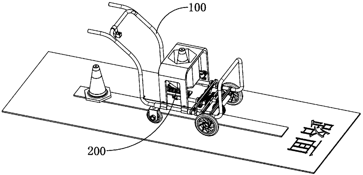
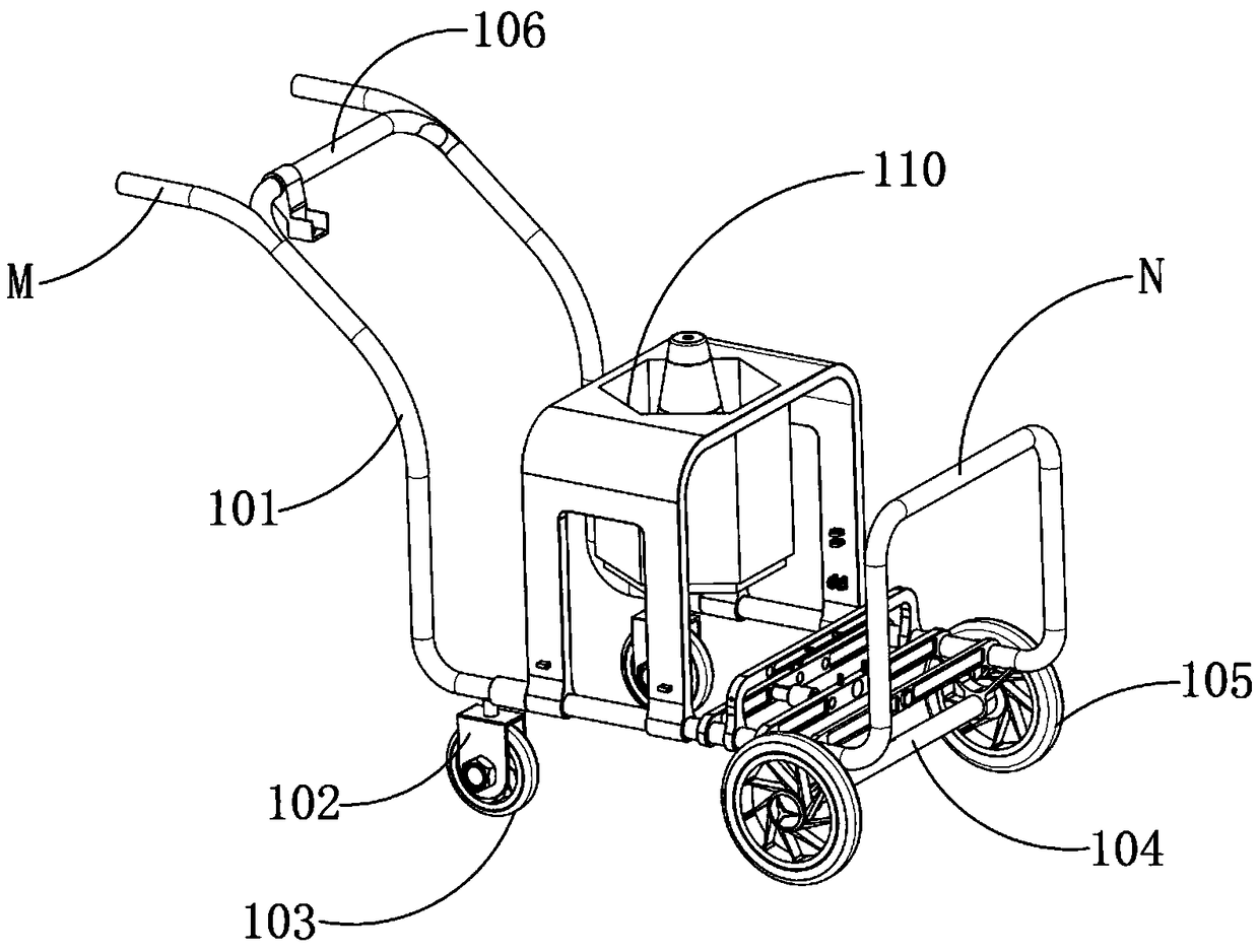
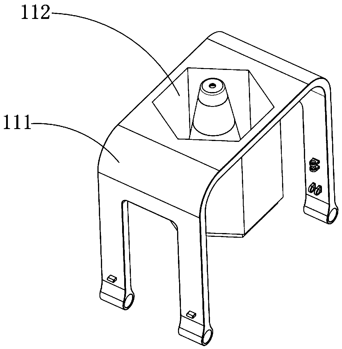
[0050] see Figure 1-28 , a trolley for automatically placing road cones applied to municipal roads, which includes a trolley body 100, on which a storage member 110 for accommodating road cones 113 is arranged, and is used to place the road cones 113 in the storage member 110 one by one Placed automatic drop device 200, the automatic drop device 200 includes a limit support mechanism 210 for supporting the road cone 113, a transmission for driving the limit sup...


PUM


Abstract

The invention provides a construction cart for automatic traffic cone arrangement and placement. The construction cart comprises a cart body. The cart body is provided with a storage component for storing traffic cones and an automatic placing and falling device for placing the traffic cones in the storage component one by one. The automatic placing and falling device comprises a limiting supporting mechanism for supporting the traffic cones, a transmission mechanism used for driving the limiting supporting mechanism not to support the traffic cones one by one, and a power source for providingpower for the transmission mechanism. The transmission mechanism is set into an idling state, an acceleration state and a deceleration state, all of which can be mutually switched, wherein the initial state is the idling state. The transmission mechanism comprises a transmission shaft connected with the power source and a speed changing shaft connected with the limiting supporting mechanism. A speed changing component is arranged between the transmission shaft and the speed changing shaft and comprises an acceleration component and a deceleration component. The transmission mechanism furthercomprises a combination control component for controlling transmission of the acceleration component or transmission of the deceleration component.

Description

technical field [0001] The invention relates to the technical field of municipal road management, in particular to a construction trolley for automatic arrangement and placement of road cones. Background technique [0002] Road cones, also known as roadblocks, are used to place in the middle of the road, dangerous areas and road construction sites, etc., and are located around places that need to temporarily separate traffic flow, guide traffic, guide vehicles to bypass dangerous road sections, protect construction site facilities and personnel, or other appropriate Location, generally used in urban intersection lanes, highway maintenance, traffic police law enforcement, road law enforcement, hotels, residential areas, sports venues, dangerous areas, road construction and other areas. Road cones have good flexibility, anti-car rolling, hard object impact No damage, anti-sun, not afraid of wind and rain, heat-resistant, cold-resistant, and no cracks. During its use, the road ...

Claims


Application Information

Patent Timeline
Patent Type & Authority Applications(China)
IPC IPC(8): E01F9/70
CPCE01F9/70
Inventor 不公告发明人
Owner 张伟
Why Eureka
Try Eureka