
Cylindrical roller bearing retainer and processing method

A cylindrical roller bearing and processing method technology, applied in the field of bearing processing, can solve problems such as fracture and pocket wear, and achieve the effects of avoiding stress concentration, improving impact resistance, and ensuring use reliability and safety.

Inactive Publication Date: 2019-02-22
AVIC HARBIN BEARING
View PDF12 Cites 2 Cited by
  • Summary
  • Abstract
  • Description
  • Claims
  • Application Information

AI Technical Summary

Problems solved by technology

[0003] The problem to be solved by the invention is: the problem that the existing bearing cage will be worn and broken during the use process

Method used


Image

  • Cylindrical roller bearing retainer and processing method
  • Cylindrical roller bearing retainer and processing method
  • Cylindrical roller bearing retainer and processing method

Examples


specific Embodiment approach 1

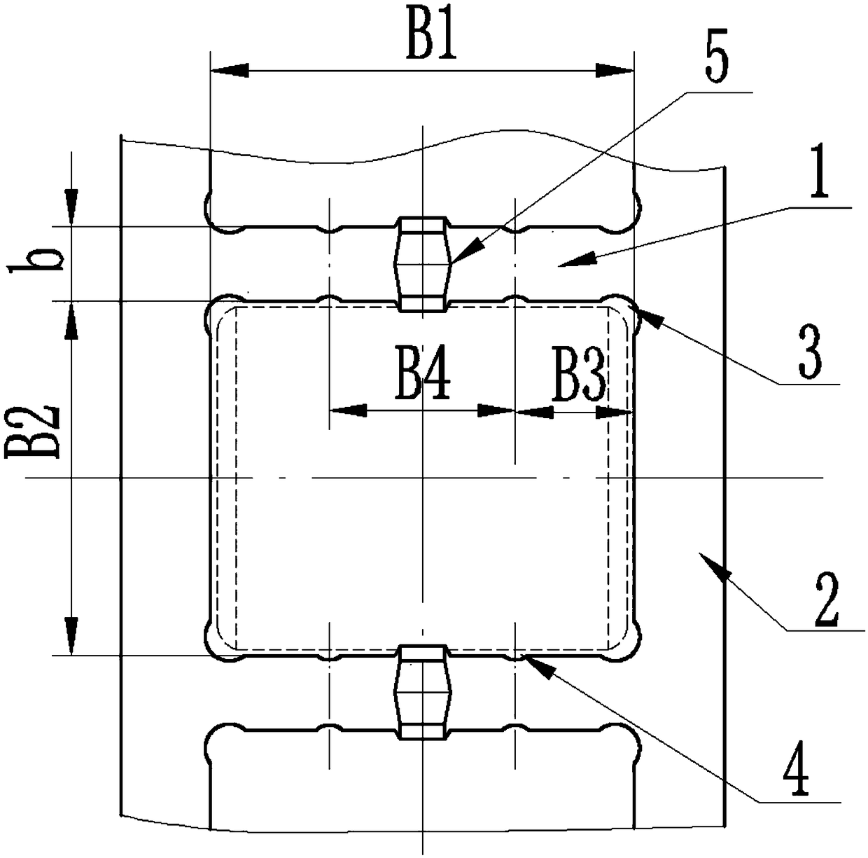
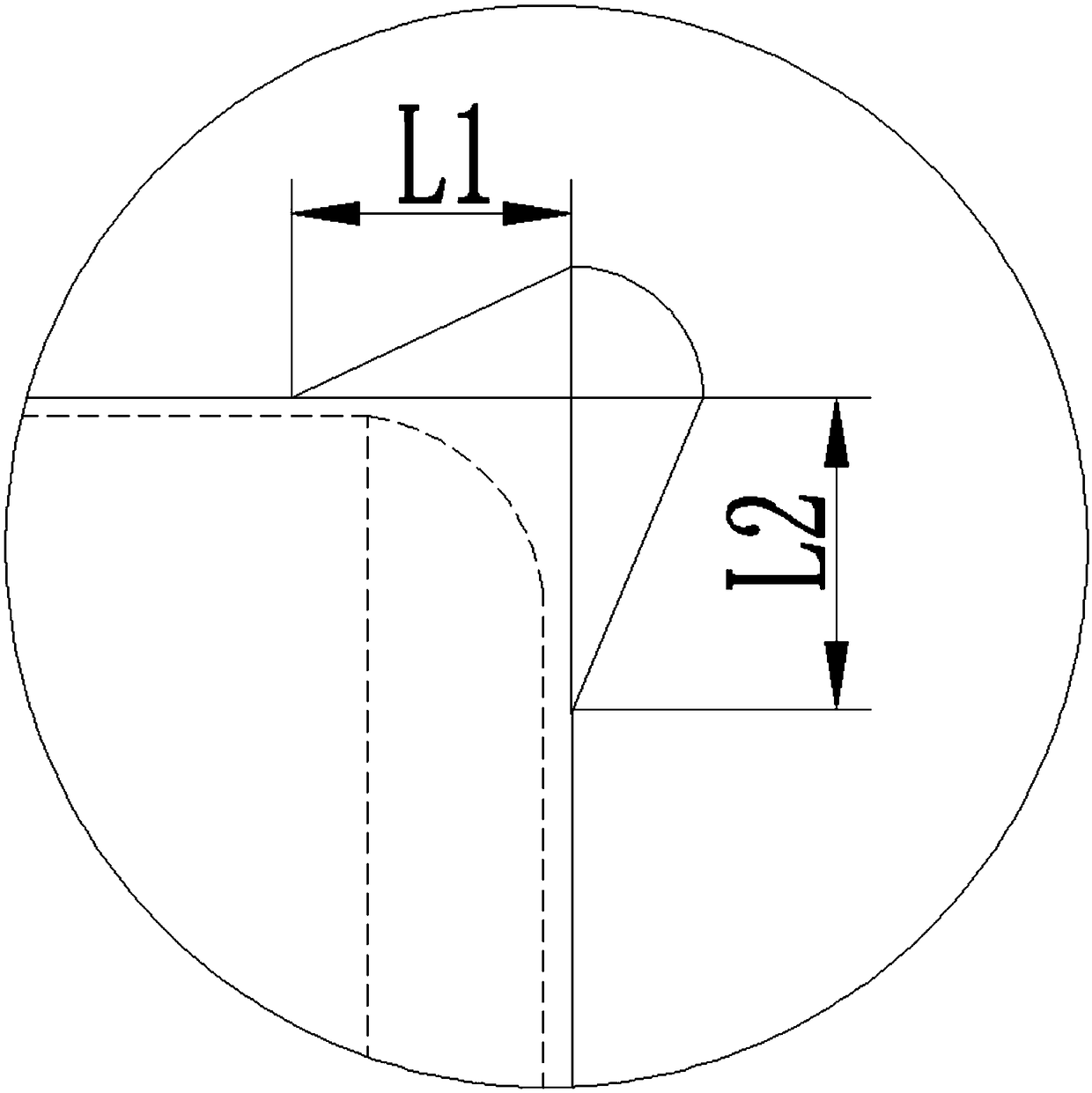
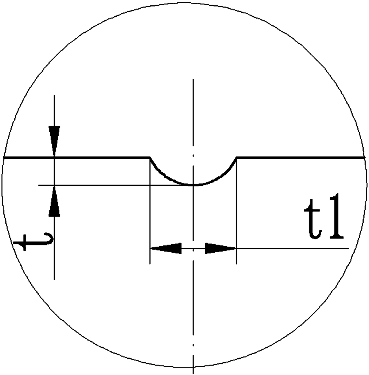
[0033] Specific implementation mode one: the following combination figure 1 This embodiment will be specifically described. In this embodiment, a cylindrical roller bearing cage includes a body 2 and a beam 1, and a stress buffer groove 3 is processed at the transition position between the body 2 and the beam 1, and the stress buffer groove 3 is 2 / 3 to 3 / 4 circles, the beam 1 is processed with an oil groove 4, the oil groove 4 is a semicircle concave along the radial direction of the beam 1, the number of oil grooves 4 is N, and N is a positive integer.

[0034] Working principle: Design the stress buffer groove 3 at the transition position between the cage pocket beam and the lintel, the stress buffer groove 3 is 2 / 3 to 3 / 4 circular, because of its shape characteristics, the transition between the body 2 and the beam 1 The position stress is dispersed to avoid stress concentration and cracks due to insufficient size transition between the two. A longitudinal oil groove is d...

specific Embodiment approach 2

[0035] Specific embodiment 2: This embodiment is a further description of specific embodiment 1. In this embodiment, a single locking point 5 is provided in the middle of the beam 1 to ensure that the come out.

specific Embodiment approach 3

[0036] Embodiment 3: This embodiment is a further description of Embodiment 1. In this embodiment, the oil groove 4 is a longitudinal oil groove.


PUM

PropertyMeasurementUnit
verticalityaaaaaaaaaa

Abstract

The invention relates to a cylindrical roller bearing retainer and relates to the field of bearing processing. In order to solve the problem that a pocket of an existing bearing retainer in a using process is worn and broken, the device comprises a body and a cross beam. A stress buffer slot which is a 2 / 3 to 3 / 4 circle is processed in a transitional position of the body and the cross beam. N Oiltanks are processed in the cross beam. The oil tanks are semicircles which are sunken along the radial direction of the cross beam. N is a positive integer. By adopting the device, a phenomenon of stress concentration can be avoided, the shock resistance of the retainer is improved greatly, and the problems of cracks and raptures at the corners of the pocket can be solved. The using reliably and safety of a product bearing are guaranteed as a result of the structural design and the dimensional precision control of the pocket of the retainer. The reliability index of the bearing can be improvedto 1.3 times. The device can be widely applied to the field of bearing processing.

Description

technical field [0001] The invention relates to the field of bearing processing, in particular to a bearing cage. Background technique [0002] At present, the dn value of domestic aero-engine main shaft bearings has reached 3.5×10 6 , the working temperature is above 315°C. With the continuous improvement of the performance of my country's aircraft, the requirements for high speed, high temperature and operational stability of aero-engine bearings are also continuously increasing. For this type of high-performance bearings, except for the rings and rolling bodies, the refined design of the structural dimensions of each part of the cage has gradually attracted attention and attention. During the use of engine main shaft bearings, pocket wear and even fractures continue to occur. . Contents of the invention [0003] The problem to be solved by the invention is: the problem of wear and fracture of the pocket holes in the existing bearing cage during use. [0004] The pres...

Claims


Application Information

Patent Timeline
Patent Type & Authority Applications(China)
IPC IPC(8): F16C33/46F16C33/66B23P15/00
CPCB23P15/00B23P15/003F16C33/46F16C33/6637
Inventor 赵燕佐景涛闫国斌石东丹刘雨健刘颖志
Owner AVIC HARBIN BEARING
Learn More