
Multifunctional combined type pipe clamp

A combined and multi-functional technology, applied in the direction of pipe supports, pipes/pipe joints/fittings, mechanical equipment, etc., can solve the problems of the connection structure damage between the upper clamp seat and the lower clamp seat, the damage of the pipeline line, and the inability to adjust the pipeline, etc. It achieves the effects of good support effect, improved flexibility of use, and avoidance of damage

Inactive Publication Date: 2019-02-22
慈溪铭展工贸有限公司
View PDF0 Cites 2 Cited by
  • Summary
  • Abstract
  • Description
  • Claims
  • Application Information

AI Technical Summary

Problems solved by technology

[0003] The usual structure of the existing pipe clamps is that the upper clamping seat and the lower clamping seat clamp the pipe between the two groups, and the two ends are fixed by fastening bolts. Since the structure between the upper clamping seat and the lower clamping seat is relatively independent, in There is some inconvenience in the process of installing the pipeline. In addition, the traditional pipeline clamp only clamps the pipeline and does not have other functions. For example, it cannot be adjusted according to the actual width of the pipeline. , the pipeline will sway, which will cause a certain amount of extrusion between the upper clamp seat and the lower clamp seat, so that the connection structure between the upper clamp seat and the lower clamp seat will be damaged, which will cause damage to the pipeline line, so in the process of use , has brought certain influence, for this reason, we propose a multi-functional combined pipe clamp

Method used

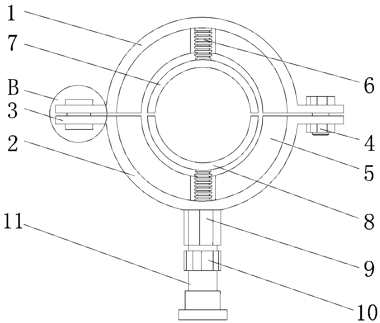
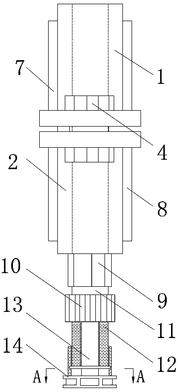
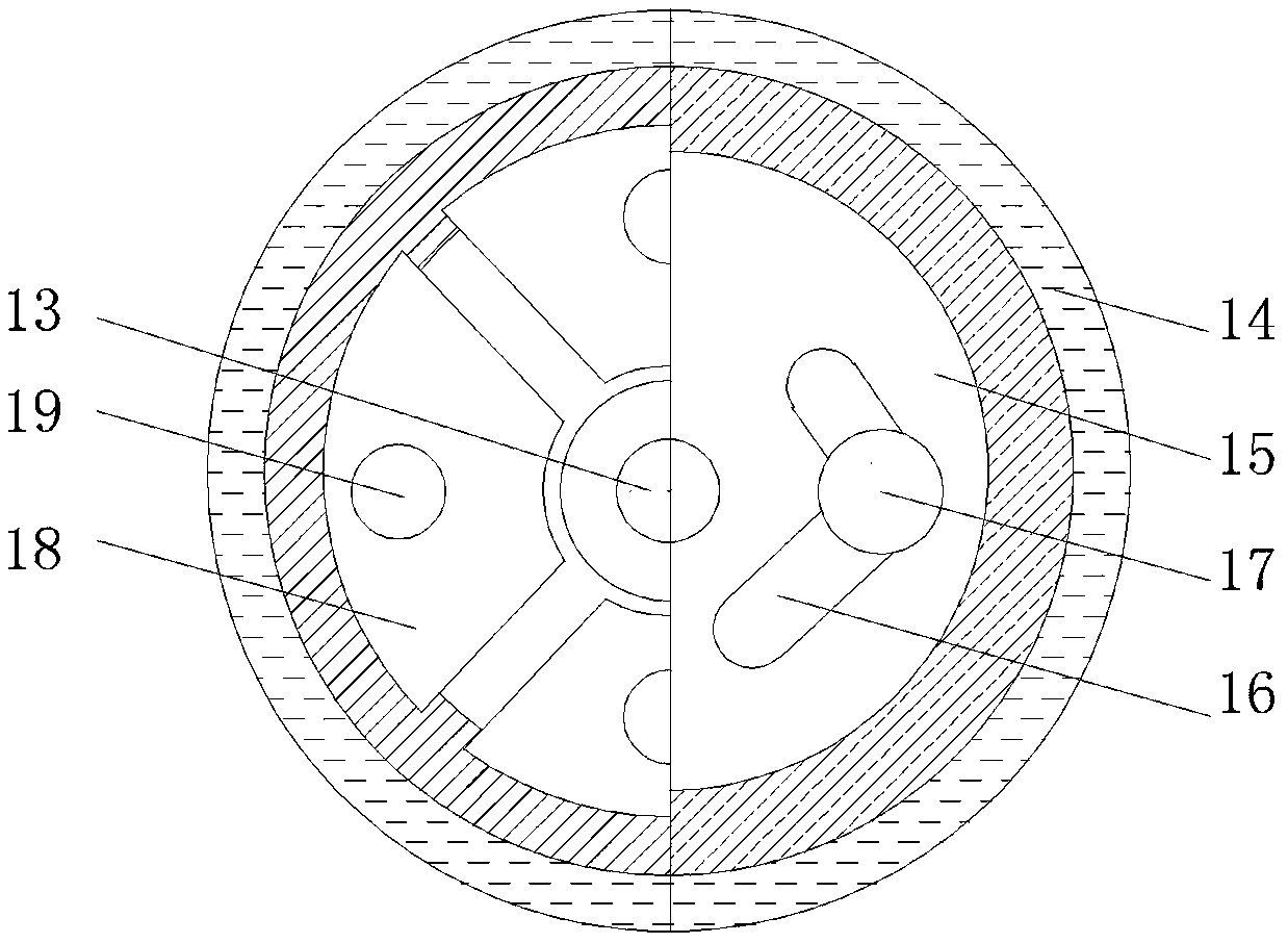

Image

  • Multifunctional combined type pipe clamp
  • Multifunctional combined type pipe clamp
  • Multifunctional combined type pipe clamp

Examples


Embodiment Construction

[0027] The following will clearly and completely describe the technical solutions in the embodiments of the present invention with reference to the accompanying drawings in the embodiments of the present invention. Obviously, the described embodiments are only some, not all, embodiments of the present invention. Based on the embodiments of the present invention, all other embodiments obtained by persons of ordinary skill in the art without making creative efforts belong to the protection scope of the present invention.

[0028] In the description of the present invention, it should be noted that the terms "center", "upper", "lower", "left", "right", "vertical", "horizontal", "inner", "outer" etc. The indicated orientation or positional relationship is based on the orientation or positional relationship shown in the drawings, and is only for the convenience of describing the present invention and simplifying the description, rather than indicating or implying that the referred d...


PUM


Abstract

The invention discloses a multifunctional combined type pipe clamp. The multifunctional combined type pipe clamp comprises an upper clamping seat and a lower clamping seat, wherein an adjusting mechanism is arranged at the end, which is close to the lower clamping seat, of the upper clamping seat in the horizontal direction; the end, which is away from the adjusting mechanism, of the upper clamping seat is fixedly connected with a fastening bolt; substrates are separately arranged on the inner side wall of the upper clamping seat and the inner side wall of the lower clamping seat; the sides, which are close to vertical central axes of the substrates, of the upper clamping seat and the lower clamping seat are separately connected with spring columns by bolts; the ends, which are away from the upper clamping seat and the lower clamping seat, of the spring columns are separately connected with a first clamping portion and a second clamping portion by bolts; a threaded cap is welded to theouter surface of the bottom of the lower clamping seat; and a knob is arranged under the threaded cap. According to the multifunctional combined type pipe clamp, a pipe is convenient to mount owing to the combined type, furthermore, structure buffering performance is achieved, meanwhile, the pipe clamp can be adjusted according to the actual width of the pipe, thus, the using flexibility of the pipe clamp is improved, moreover, a good supporting effect is achieved, and the application prospect is good.

Description

technical field [0001] The invention relates to the field of pipe clamps, in particular to a multifunctional combined pipe clamp. Background technique [0002] As the name suggests, the pipe clamp is an auxiliary tool for clamping the pipeline. During the laying of large-scale pipelines, due to the long laying stroke of the pipeline, more pipe clamps are needed to support the pipeline to ensure the smooth laying of the pipeline. The main application It is widely used in the layout process of pipelines in electric power, metallurgy, petroleum, chemical industry and other industries. [0003] The usual structure of the existing pipe clamps is that the upper clamping seat and the lower clamping seat clamp the pipe between the two groups, and the two ends are fixed by fastening bolts. Since the structure between the upper clamping seat and the lower clamping seat is relatively independent, in There is some inconvenience in the process of installing the pipeline. In addition, th...

Claims


Application Information

Patent Timeline
Patent Type & Authority Applications(China)
IPC IPC(8): F16L3/10F16L3/205F16L3/16
CPCF16L3/1075F16L3/16F16L3/2056
Inventor 叶鑫
Owner 慈溪铭展工贸有限公司
Learn More