
Stripping forcing system for separation and stripping electric connector on launch vehicle

A technology for electrical connectors and launch vehicles, which is applied in the direction of connection/disconnection of connecting devices, and can solve the problems of separation and disconnection of electrical connectors and failure of automatic detachment

Inactive Publication Date: 2015-12-16
BEIJING INST OF SPACE LAUNCH TECH +1
View PDF2 Cites 6 Cited by
  • Summary
  • Abstract
  • Description
  • Claims
  • Application Information

AI Technical Summary

Problems solved by technology

[0003] Before the rocket is launched, the separation and separation electrical connector needs to be separated from the rocket. Under normal circumstances, the locking and separation mechanism can automatically disengage from the launch vehicle, that is, the separation and separation electrical connector can automatically fall off, but there will also be separation and separation The situation where the electrical connector fails to fall off automatically occurs

Method used


Image

  • Stripping forcing system for separation and stripping electric connector on launch vehicle
  • Stripping forcing system for separation and stripping electric connector on launch vehicle

Examples


Embodiment 1

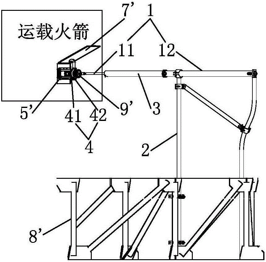
[0021] Such as figure 1 As shown, embodiment 1 of the strong release system for the separation and separation of the launch vehicle electrical connector of the present invention includes a gas distribution box, a cylinder 1, and a locking sleeve 3, and the locking sleeve 3 and the cylinder 1 are arranged horizontally, and the cylinder 1 includes a cylinder barrel 12 and the piston rod 11 arranged in the cylinder 12, the axis of the piston rod 11 coincides with the axis of the cylinder 12, and the gas distribution box is used to supply air to the cylinder 1, and the gas distribution box is not shown.

[0022] The locking sleeve 3 is located on one side of the cylinder 12 and one end of the locking sleeve 3 is fixedly connected to one end of the cylinder 12, the axis of the locking sleeve 3 coincides with the axis of the cylinder 12, and the locking sleeve 3 is set Outside the piston rod 11, that is, one end of the piston rod 11 passes through and extends out of the locking slee...

Embodiment 2

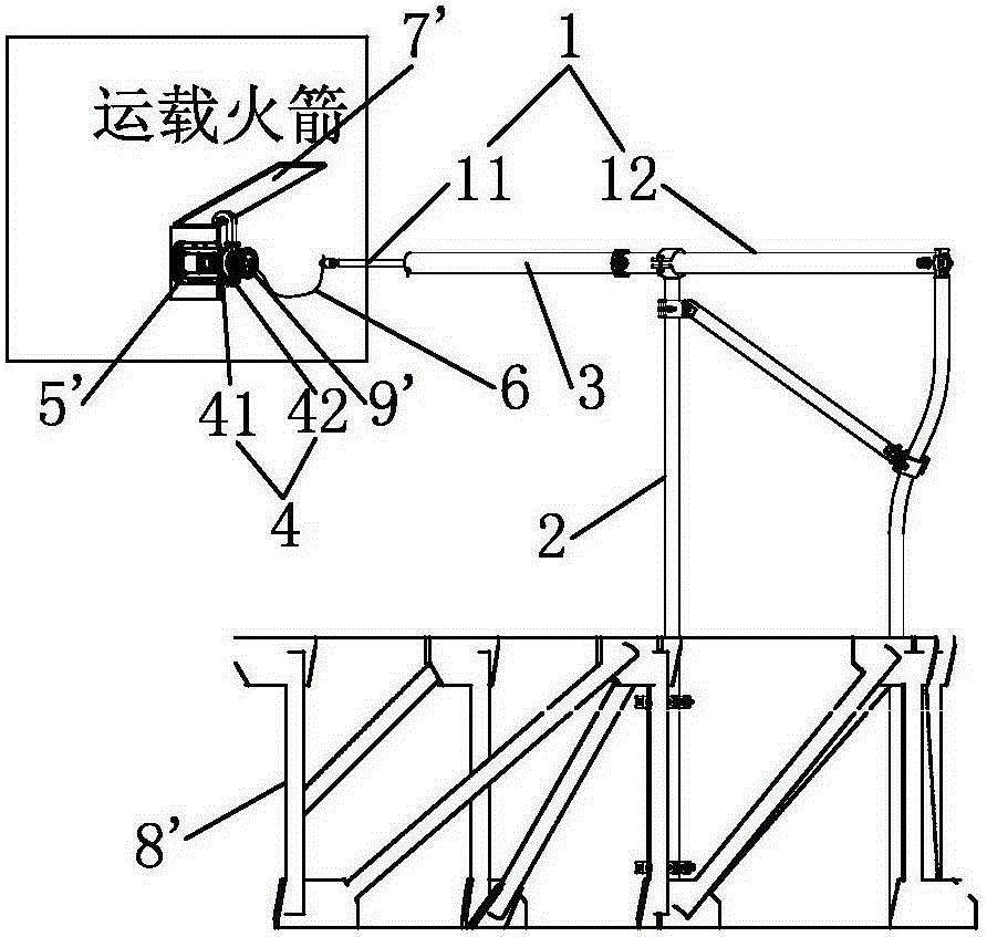
[0030] Such as figure 2 As shown, the difference between Embodiment 2 and Embodiment 1 of the release system of the carrier rocket separation and release electrical connector of the present invention is that it also includes a steel wire 6, the piston rod 11 is connected with the locking and separating mechanism 9' through the steel wire 6, and one end of the steel wire 6 It is fixedly connected with the locking and separating mechanism 9 ′, and the other end of the steel wire 6 is fixedly connected with the piston rod 11 . The cylinder 1 pulls the steel wire 6, and the steel wire pulls the locking and separating mechanism 9' of the detached electrical connector 5' to unlock, so that the detached and detached electrical connector 5' is separated from the launch vehicle, and the steel wire 6 is used to realize the flexible connection. It can adapt to the shaking of the rocket body of the launch vehicle, that is, when the rocket body of the launch vehicle shakes, the invention ...


PUM


Abstract

The invention discloses a stripping forcing system for a separation and stripping electric connector on a launch vehicle, relating to a separation and stripping forcing system for separating a rocket electric system with a ground electric system. The invention aims to provide a stripping forcing system capable of ensuring that the separation and stripping electric connector is reliably separated, locked and fixed before a rocket is launched. The stripping forcing system for the separation and stripping electric connector on the launch vehicle comprises a gas distribution box, a gas cylinder and a locking sleeve, wherein the gas distribution box is used for supplying gas to the gas cylinder, the locking sleeve is sleeved outside a piston rod of the gas cylinder, one end of the locking sleeve is fixedly connected with a cylinder of the gas cylinder, and the piston rod of the gas cylinder is connected with a locking separation mechanism.

Description

technical field [0001] The invention relates to a forced separation and shedding system, in particular to a forced separation and shedding system for separating a rocket electrical system from a ground electrical system. Background technique [0002] The launch vehicle is equipped with a separation and separation electrical connector, which is used for connection and separation between the electrical system on the rocket and the ground electrical system. The separation and separation electrical connector includes a locking separation mechanism, which is plugged into the on the launch vehicle. By locking the separation mechanism, the separation and separation electrical connector is connected to the launch vehicle, and the launch vehicle is provided with a cover plate, and the cover plate should not affect the separation and separation of the separation and separation electrical connector when falling off. [0003] Before the rocket is launched, the separation and separation...

Claims


Application Information

Patent Timeline
Patent Type & Authority Applications(China)
IPC IPC(8): H01R43/26
Inventor 陈传宝沈福东苗利蕾樊志强刘伟建雷达理何燚赵立乔赵忠明霍卫星
Owner BEIJING INST OF SPACE LAUNCH TECH
Learn More