Low-temperature tester

A low-temperature test and tester technology, applied in the direction of instruments, measuring devices, scientific instruments, etc., can solve the problems of reducing the experimental accuracy and poor stability of low-temperature testers, and achieve the effect of stable, good stability and convenient lifting of the device

Inactive Publication Date: 2019-02-22
WUHAN YANRUN TECH DEV CO LTD
View PDF8 Cites 1 Cited by
  • Summary
  • Abstract
  • Description
  • Claims
  • Application Information

AI Technical Summary

Problems solved by technology

[0004] Aiming at the deficiencies of the prior art, the present invention provides a low temperature tester, which has the advantages of good stability, and solves the problem of poor stability of the existing low temperature tester, thereby reducing the experimental accuracy of the low temperature tester

Method used


Image

  • Low-temperature tester
  • Low-temperature tester
  • Low-temperature tester

Examples


Embodiment 2

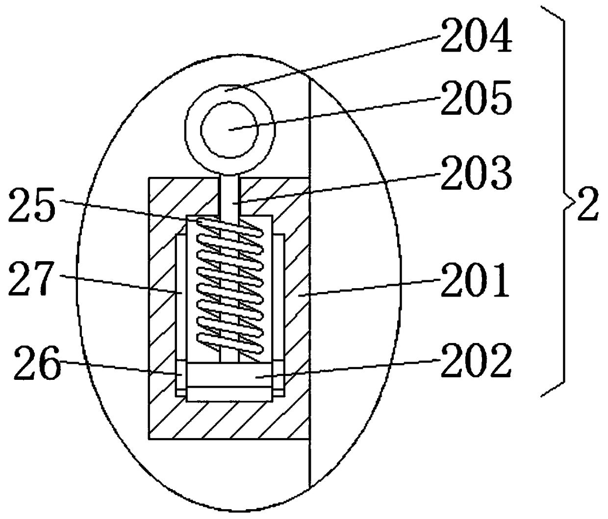
[0034] Embodiment 2: The difference from Embodiment 1 is that the hoisting mechanism 2 includes a card box 201, the side of the card box 201 close to the low temperature test device 1 is fixedly connected with the low temperature test device 1, and the inside of the card box 201 is movably connected with a slide plate 202, The top of the slide plate 202 is fixedly connected with a second fixed rod 203, the top of the second fixed rod 203 runs through the card box 201 and extends to the top of the card box 201, the top of the second fixed rod 203 is fixedly connected with a pull block 204, and the pull block 204 There is a through hole 205 in the inside. By setting the lifting mechanism 2, the disassembly and assembly on the market is more complicated and the height of the device will be increased. However, this structure can make it easier for users to lift the device without disassembly and assembly. The purpose of reducing the height of the device is to facilitate the movemen...

Embodiment 3

[0035] Embodiment 3: The difference from Embodiment 1 is that the anti-collision mechanism 3 includes a telescopic tube 301, the side of the telescopic tube 301 close to the low temperature test device 1 is fixedly connected to the low temperature test device 1, and the telescopic tube 301 is away from the side of the low temperature test device 1. The side is fixedly connected with the sixth fixed block 302, the top and the bottom of the sixth fixed block 302 are fixedly connected with the guide block 303, the surface of the telescopic tube 301 is provided with the first spring 304, by setting the anti-collision mechanism 3, the It is easy to cause force deviation, but this structure can make the device move in the direction of the telescopic tube 301 when it is hit by an external force, so as to achieve the purpose of uniform force, which is convenient for users to use and improves the service life of the device , increasing the practicability of the device.

Embodiment 4

[0036] Embodiment 4: The difference from Embodiment 2 is that: the surface of the second fixed rod 203 is covered with a second spring 25, both sides of the slide plate 202 are fixedly connected with a second slider 26, and both sides of the inner wall of the card box 201 are fixed. There is a second chute 27 for use with the second slider 26. By setting the second spring 25, the second slider 26 and the second chute 27, it is easy to cause the rotation of the second fixed rod 203 on the market, which is inconvenient. For hoisting, but this structure can avoid the rotation of the second fixed rod 203, and at the same time ensure that the second fixed rod 203 is in a fixed position, which is convenient for the user to hoist and improve the practicability of the device.


PUM


Abstract

The invention discloses a low-temperature tester. The low-temperature tester comprises a low-temperature testing device, wherein hoisting mechanisms are arranged on the tops of the two sides of the low-temperature testing device, anti-collision mechanisms are arranged at the bottoms of the two sides of the low-temperature testing device, the bottom of the low-temperature testing device is fixedlyconnected with a transmission box, a rotating disc is arranged on the right side of the transmission box, a movable column is fixedly connected to the left side of the rotating disc, the left side ofthe movable column penetrates through the transmission box and extends into the transmission box, and the left side of the movable column is fixedly connected with a first screw rod. According to thelow-temperature tester, the purpose of contacting and separating universal wheels from the ground is achieved by moving up and down fourth fixing blocks, the effect of moving and fixing the device isachieved, and therefore the purpose of stabilizing the device is achieved, and the problem that because the stability of an existing low-temperature tester is poor, the experiment precision of the low-temperature tester is reduced is solved; and the low-temperature tester has the advantages of being good in stability and convenient to use by users.

Description

technical field [0001] The invention relates to the technical field of low temperature testers, in particular to low temperature testers. Background technique [0002] The low temperature tester is used for reliability tests at low temperatures. It is used for the parts and materials of related products such as electronics, automobiles and motorcycles, aerospace, rubber, plastics, metals, ship weapons, colleges and universities, scientific research units, etc. under the condition of low temperature changes. , to test its performance indicators. Material performance testing requires the use of a low-temperature tester, but the existing low-temperature tester has poor stability, which reduces the experimental accuracy of the low-temperature tester, making it inconvenient for users to use the low-temperature tester and reducing the practicability of the low-temperature tester . Contents of the invention [0003] (1) Solved technical problems [0004] Aiming at the deficien...

Claims


Application Information

Patent Timeline
Patent Type & Authority Applications(China)
IPC IPC(8): F16M11/20G01N25/00
CPCF16M11/20G01N25/00
Inventor 向际高向凌魏吴代施
Owner WUHAN YANRUN TECH DEV CO LTD
Why Eureka
Try Eureka