
Obstacle shadow shielding calculation method on different roof conditions

A technology of shadow occlusion and calculation method, applied in complex mathematical operations, control using feedback, etc., can solve problems such as affecting income, fire, power generation loss, etc., and achieve good results in refined design

Active Publication Date: 2019-02-22
远景能源(南京)软件技术有限公司 +1
View PDF8 Cites 6 Cited by
  • Summary
  • Abstract
  • Description
  • Claims
  • Application Information

AI Technical Summary

Problems solved by technology

[0004] In general, the hot spot effect will not only bring the risk of fire, but also bring a large amount of power loss and affect the income

Method used


Image

  • Obstacle shadow shielding calculation method on different roof conditions
  • Obstacle shadow shielding calculation method on different roof conditions
  • Obstacle shadow shielding calculation method on different roof conditions

Examples


Embodiment Construction

[0035] A calculation method for shadow occlusion of obstacles under different roof conditions, specifically comprising the following steps:

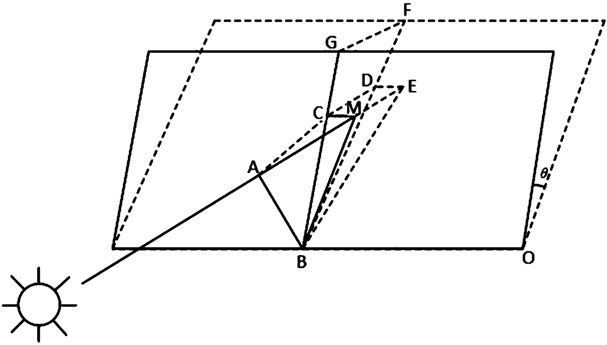
[0036] 1. If figure 1 The schematic diagram of the parameters in the calculation method of obstacle shadow occlusion under different roof conditions is shown, θ is the slope angle of the roof, the solid frame line is the roof, the virtual frame line is the horizontal plane, the roof and the horizontal plane intersect on the straight line OB, and the height of the obstacle AB is l(AB The height is the distance parallel to the normal direction of the roof, that is, the height relative to the roof). Draw a straight line BF perpendicular to OB from point B on the horizontal plane, draw a straight line BG perpendicular to OB on the roof plane from point B, draw MC on the roof plane perpendicular to BC, and draw ED on the horizontal plane perpendicular to BF. The projection of obstacle AB on the roof is BM, the component of BM perpendicular t...


PUM


Abstract

The invention relates to an obstacle shadow shielding calculation method on different roof conditions. On the basis of information including a slope angle an azimuth angle of a roof, an obstacle height, a sun azimuth, and a sun elevating angle of a roof, projection of an obstacle on the roof is determined and components of the projection in a north-south direction and an east-west direction of theroof; and according to information of the slope angle and the orientation of the roof, components of the obstacle in all directions of the roof are calculated precisely at any time, thereby providingthe important in parameters for the refined design of the photovoltaic power station. Compared with the traditional industrial way of determining the shielding range only based on the experience, theobstacle shadow shielding calculation method has the following advantages: the shadow shielding range of an obstacle on a horizontal plane in any time range can be calculated and the shadow shieldingrange of the roof obstacle any an azimuthal angle and a gradient angle in any time range can be calculated, so that the refined design of the photovoltaic system is guided well.

Description

technical field [0001] The invention relates to a photovoltaic technology, in particular to a calculation method for shadow shielding of obstacles under different roof conditions. Background technique [0002] During the actual operation of photovoltaic power plants, due to the occlusion of surrounding buildings, trees, clouds, etc., photovoltaic arrays are often in partial shadows. Parallel connection of bypass diodes at both ends of a certain number of battery strings can effectively avoid hot spots caused by uneven distribution of light, but at the same time it will also complicate the output characteristics of the photovoltaic array. [0003] Hot spot effect: Under certain conditions, the shaded solar cell module in a series branch will be used as a load to consume the energy generated by other illuminated solar cell modules, and the shaded solar cell module will heat up at this time. This is the hot spot effect. The hot spot effect can seriously damage the solar cells...

Claims


Application Information

Patent Timeline
IPC IPC(8): G05D3/12G06F17/15
CPCG05D3/12G06F17/15
Inventor 李舟生昌菁徐宁孙捷张磊刘金龙
Owner 远景能源(南京)软件技术有限公司
Learn More