Insulated voltage-resistant test tool for power battery module

A power battery and module insulation technology, which is applied in the direction of secondary batteries, circuits, electrical components, etc., can solve the safety hazards of sharp corners at the welding point to the digital model, and the problems of bruising and metal particles attached to the battery during handling and moving , to achieve the effect of solving the micro-short circuit problem

Pending Publication Date: 2019-02-22
江苏和中普方新能源科技有限公司
View PDF0 Cites 0 Cited by
  • Summary
  • Abstract
  • Description
  • Claims
  • Application Information

AI Technical Summary

Problems solved by technology

[0002] At present, after the CMT of the side plate of the existing battery digital model, there may be sharp corners at the welding point, which poses a safety hazard to the digital model. At the same time, there is a possibility of scratches and metal particles attached during the handling and movement of the battery cell. Most

Method used


Image

  • Insulated voltage-resistant test tool for power battery module
  • Insulated voltage-resistant test tool for power battery module
  • Insulated voltage-resistant test tool for power battery module

Examples


Embodiment approach 1

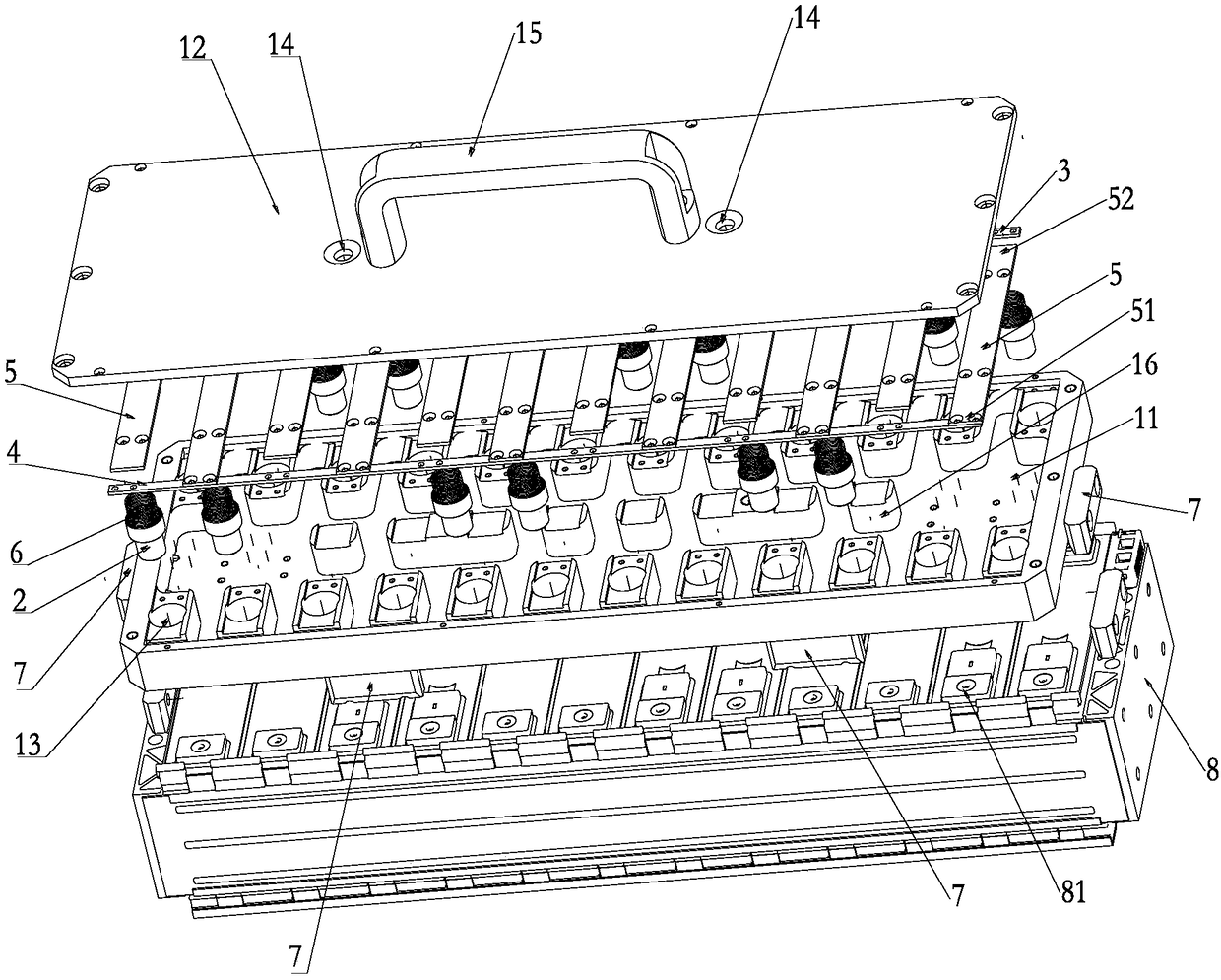
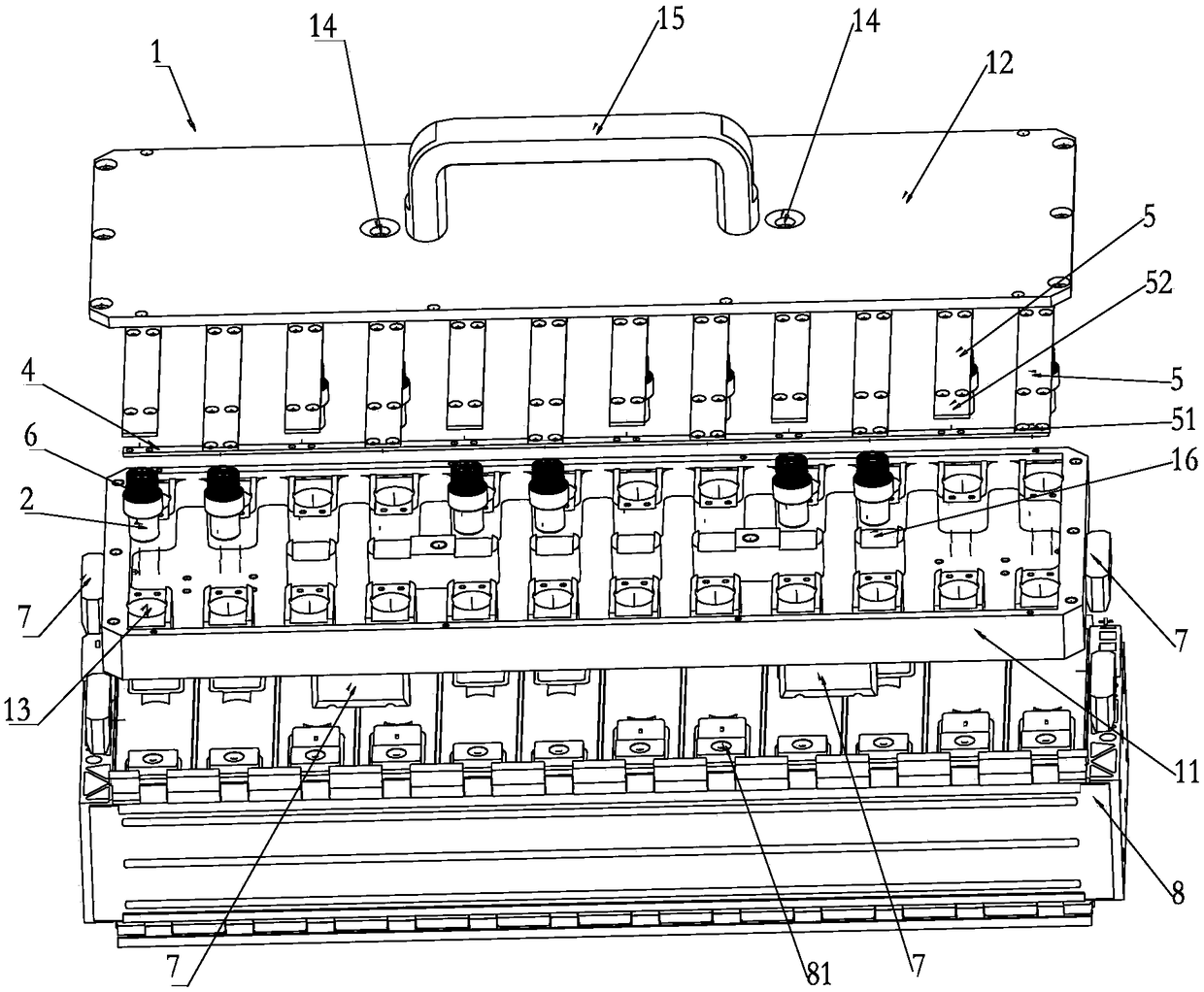
[0040] Implementation mode one: if figure 1 and figure 2 As shown, the two main road copper strips are respectively the first main road copper strip 3 and the second main road copper strip 4; several branch copper strips 5 are located between the first main road copper strip 3 and the second main road copper strip. Between the main road copper bars 4; the branch copper bars 5 connected to the first main road copper bars 3 and the branch copper bars 5 connected to the second main road copper bars 4 are alternately arranged one by one;

[0041] The connection end 51 of the branch copper strip 5 connected to the first main circuit copper strip 3 is connected with a test probe 2, and the branch copper strip 5 connected to the second main circuit copper strip 4 In addition, in order to make the connection more stable, the floating end 52 of the branch copper strip 5 connected to the end of the first main road copper strip 3 is connected with the test probe 2;

Embodiment approach 2

[0042]Embodiment 2: Two main circuit copper strips and several branch circuit copper strips 5 adopt the same connection method as in Embodiment 1, the difference lies in the connection position of the test probe 2. In this embodiment, all the branch circuit copper strips The test probe 2 is connected to the floating end 52 of the bar 5 .

[0043] In Embodiment 1 and Embodiment 2, a plurality of branch copper strips 5 are interlaced one by one, so that the battery cells in the power battery module 8 can be connected in parallel first and then in series, which is convenient for connection and detection.

Embodiment approach 3

[0044] Embodiment 3: The two main road copper bars are respectively the first main road copper bar 3 and the second main road copper bar 4; several branch copper bars 5 are located between the first main road copper bar 3 and the second main road copper bar. Between the two main road copper bars 4; the branch copper bars 5 connected to the first main road copper bars 3 and the branch copper bars 5 connected to the second main road copper bars 4 are alternately arranged in pairs;

[0045] The free end 52 or connecting end 51 of the branch copper bar 5 is connected with a test probe 2; One of the connecting ends 51 or the floating end 52 of the two branch copper strips 5 is connected with the test probe 2;

[0046] Embodiment 3 The multi-branch copper strips 5 are arranged alternately in pairs, and the battery cells in the power battery module 8 are first connected in series and then in parallel, so as to facilitate connection and detection.

[0047] A preferred solution of thi...


PUM


Abstract

The invention relates to an insulated voltage-resistant test tool for a power battery module. The tool comprises a support plate, a plurality of test probes and a copper bar, wherein the plurality oftest probes are arranged on the support plate and are in one-to-one correspondence to electric core pole columns in the power battery module, and the test probes are mutually connected through the copper bar to enable electric cores in the corresponding power battery module to be connected in series or in parallel; the copper bar is partly exposed outside the support plate and used for cooperatingwith a test meter to detect the insulation voltage resistance of the power battery module. According to the insulated voltage-resistant test tool, the test probes are adopted to cooperate with the copper bar to enable the electric cores in the power battery module to be connected in series or in parallel, then the insulated voltage resistance of the power battery module can be detected through the test meter, a micro short circuit problem existing in the power battery module can be effectively detected, and the micro short circuit problem existing between the electric cores is solved after the power battery module is assembled.

Description

technical field [0001] The invention relates to the technical field of new energy power batteries, in particular to a power battery module insulation withstand voltage test tool. Background technique [0002] At present, after the CMT of the side plate of the existing battery digital model, there may be sharp corners at the welding point, which poses a safety hazard to the digital model. At the same time, there is a possibility of scratches and metal particles attached during the handling and movement of the battery cell. Most of the existing technologies are The structure of the inside of the cell and the electrical connector solves the problem of short circuit, but it fails to effectively solve the problems of short circuit or micro short circuit caused by human factors in the process of assembly and handling, and poor incoming materials. Contents of the invention [0003] The technical problem to be solved by the present invention is to provide a power battery module in...

Claims


Application Information

Patent Timeline
IPC IPC(8): H01M10/48
CPCH01M10/482Y02E60/10
Inventor 杨占军俱晨贾志佳邓翔李昱甫杨三虎
Owner 江苏和中普方新能源科技有限公司
Why Eureka
Try Eureka