Hydrographical rechargeable lithium or sodium ion battery

A sodium-ion battery, lithium-ion technology

Inactive Publication Date: 2008-04-02
FUDAN UNIV
View PDF1 Cites 73 Cited by
  • Summary
  • Abstract
  • Description
  • Claims
  • Application Information

AI Technical Summary

Problems solved by technology

However, in aqueous solution, when the lithium ion intercalation and deintercalation process reaches a certain potential, hydrogen evolution and oxygen evolution reactions will occur. It is difficult to find electrode pair materials that only undergo lithium ion intercalation and de

Method used


Image

  • Hydrographical rechargeable lithium or sodium ion battery

Examples


Embodiment 1

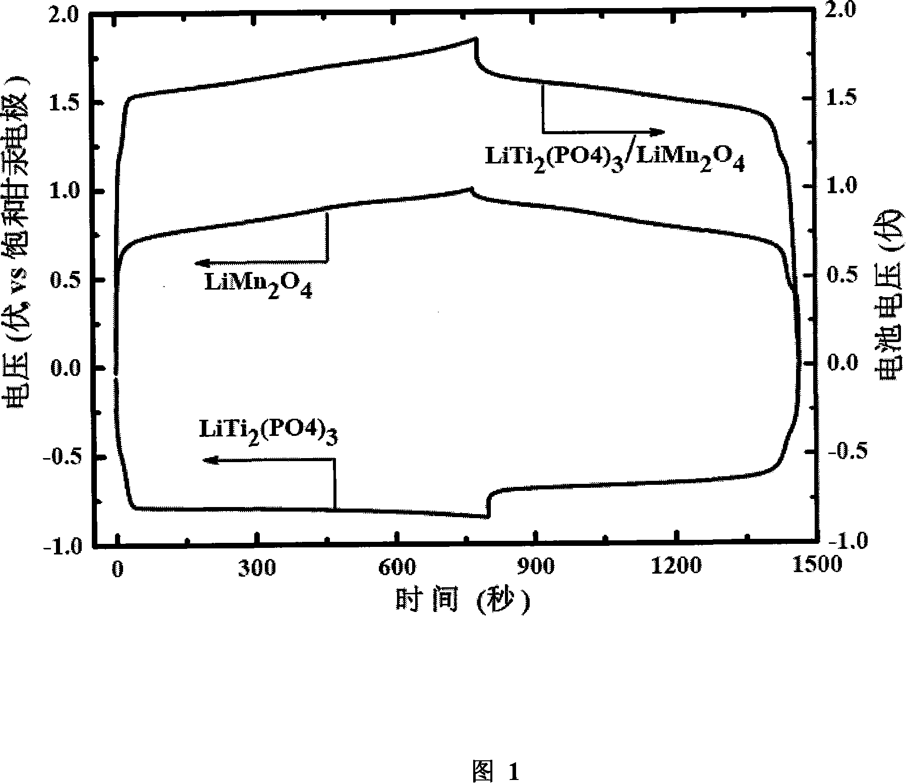
[0018] As a comparative example, the anode material is LiTi 2 (PO 4 ) 3 , the slurry ratio is according to LiTi 2 (PO 4 ) 3 : Conductive agent: Binder = 85:5:10 mixed slurry, then evenly coated on the nickel mesh current collector, dried and pressed to form an electrode. The cathode material is spinel-type LiMn for commercial lithium-ion batteries 2 o 4 . Positive electrode composition according to LiMn 2 o 4 : carbon black: binder = 85:5:10 weight ratio mixed slurry, evenly coated on the nickel mesh current collector, dried and pressed to form an electrode. In this embodiment, the actual capacity of the positive electrode material is 80mAh / g, the negative electrode is 95mAh / g, and the single-side coating amount of the positive electrode is 12mg / cm 2 , negative electrode 10mg / cm 2 . Then the two electrodes are cut according to the specifications, paired and assembled into a 2# battery (diameter 14mm*height 50mm), the diaphragm used is the diaphragm of a commercial ...

Embodiment 2

[0020] Adopt the method for vapor phase deposition to the LiTi in embodiment 1 2 (PO 4 ) 3 Carry out carbon coating modification, its synthetic method is: with the LiTi of carbon coating in embodiment 2 2 (PO 4 ) 3 The material is the bulk, placed in a tube furnace. Toluene is used as the carbon source, Ar gas is used as the gas source, the gas flow rate is controlled, and the toluene vapor is blown into the tube furnace, during which the temperature of the tube furnace is programmed to rise to the reaction temperature of 800°C. When the furnace temperature reaches the required temperature, the furnace temperature is controlled. 600min at the reaction temperature. After being cooled, it is ground to obtain the desired carbon-coated LiTi 2 (PO 4 )3 Material. The carbon content of the composite material is 5wt% as tested by thermogravimetric analysis. LiTi coated with carbon 2 (PO 4 ) 3 is the negative electrode material, and the rest are the same as in Example 1, an...

Embodiment 3

[0022] Adopt the method for vapor phase deposition to the LiTi in embodiment 1 2 (PO 4 ) 3 Carbon coating modification is carried out, and the carbon content of the composite material is 15wt% as tested by thermogravimetric analysis. LiTi coated with carbon 2 (PO 4 ) 3 is the negative electrode material, and the rest are the same as in Example 2, and the battery is prepared according to the steps and conditions in Example 1. In this embodiment, the actual capacity of the positive electrode material is 80mAh / g, the negative electrode is 80mAh / g, and the single-side coating amount of the positive electrode is 10mg / cm 2 , negative electrode 10mg / cm 2 . In the 0V-1.85V working range, the discharge current is 1C, the capacity is 40mAh / g, the average working voltage is 1.5V, and the 10C charge and discharge capacity is maintained at 34mAh / g. After 100 cycles, the capacity retention rate can reach 90% (details See Table 1).


PUM


Abstract

The invention belongs to electrochemical technical field, in particular to a novel high performance water system lithium ion battery. The invention adopts an ion embedding in-out mechanism used by an organic system lithium ion battery in an energy storage element which uses a water solution as an electrolyte. The embedding-in reaction ion mainly includes lithium ion composite and sodium ion composite. In the invention, the positive pole adopts a material containing the positive ion embedding-in composite while the negative pole adopts a shell structure material of LiTi2(PO4)3; the electrolyte adopts a water system electrolyte of the positive ion. The electric charging and discharging process only relates to the ion transfer between the two electrodes, and the invention can still has the characteristic of a rocking-chair type organic system lithium ion battery; the invention is of long cycling service life, big power, safety, low cost and no pollution, and is particularly suitable to be used as an ideal power battery of electric vehicle.

Description

technical field [0001] The invention belongs to the technical field of electrochemistry, and in particular relates to a novel high-performance water system rechargeable lithium ion battery. Background technique [0002] With the continuous development of the economy, it will inevitably lead to the depletion of natural resources such as oil and coal, environmental pollution and the aggravation of the global greenhouse effect. Human beings must grasp the balance between the "three Es" of the trinity of economic growth, environmental protection and energy supply. Now the world's annual energy consumption converted into oil is about 8 billion tons, of which 90% are fossil fuels. According to the current consumption rate, it will be exhausted in about 100 to 200 years. The comprehensive and efficient development and utilization of new energy, energy-saving technology and environmental protection technology has become a very urgent topic. The development of electric vehicles is...

Claims


Application Information

Patent Timeline
IPC IPC(8): H01M10/36H01M10/24H01M4/48H01M4/58H01M4/62
CPCY02E60/124Y02E60/10
Inventor 夏永姚罗加严李峰
Owner FUDAN UNIV
Why Eureka
Try Eureka