Ice-beating structure in cable de-icing device
An ice structure and cable technology, which is applied in the installation of cables, electrical components, overhead installation, etc., can solve the problems of poor deicing effect, etc., and achieve the effect of simple structure, easy manufacture and good use effect
- Summary
- Abstract
- Description
- Claims
- Application Information
AI Technical Summary
Problems solved by technology
Method used
Image

Examples
Embodiment Construction
[0010] The present invention will be further described below in conjunction with the accompanying drawings.
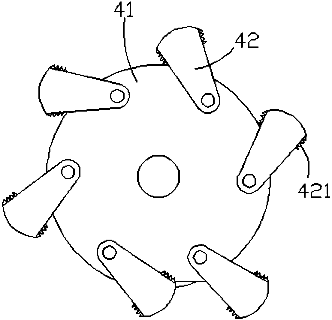
[0011] like figure 1 As shown, the ice breaking structure in a cable deicing device of the present invention includes a hitting plate 41 and a hitting block 42, and several hitting blocks 42 are hinged on the hitting plate 41 along the circumferential direction of the hitting plate 41 .
[0012] The beating block 42 is fan-shaped, and in order to ensure the beating effect of the beating block 42 , ratchets 421 are provided on both side walls of the beating block 42 .
[0013] When the present invention is in use, the beating disc 41 is fixed on the rotating shaft of the motor, the beating disc 41 rotates, and the beating block 42 hits the cable, so as to better remove the icing on the cable.
[0014] The above is only a preferred embodiment of the present invention, it should be pointed out that for those of ordinary skill in the art, some improvements can also be ma...
PUM
 Abstract
Description
Claims
Application Information
PatSnap Eureka turns technology decisions into work you can execute. Powered by our Innovation Knowledge Graph, it runs expert workflows across engineering, life sciences, materials and intellectual property. Get your review-ready output in minutes.


