
Water cup for boiling water

A water cup and cup body technology, which is applied in the field of boiling water cups, can solve problems such as potential safety hazards, unstable power supply connections, and exposed UMC concave holes, so as to achieve safe and stable power supply and increase the safety of electricity consumption

Inactive Publication Date: 2019-02-26
广西南宁东能科技有限责任公司
View PDF0 Cites 0 Cited by
  • Summary
  • Abstract
  • Description
  • Claims
  • Application Information

AI Technical Summary

Problems solved by technology

[0002] At present, boiling water cups are widely used. When using the boiling water cups, they need to be powered on first. The cup body is basically powered on by directly inserting the plugs connected to it into the power connection concave holes of the power transmission base, and the power transmission base is connected to the mains. It is always in the power-on state. Although this matching method is relatively simple and convenient to operate, the length of the cable between the post and the cup is different. After the post is inserted into the concave hole of the UMC, there is no other locking device for the post. Locking, when the cable is accidentally kicked and bumped, it will cause the post to be detached from the concave hole of the UMC, resulting in a sudden power failure of the cup, and in severe cases, it will directly cause damage to the cup. Therefore, the existing plug There is an unstable power supply connection between the column and the UMC concave hole. In addition, when the cup is not in use, the post is often pulled out from the UMC concave hole, which will cause the UMC concave hole to be exposed. It is a big safety hazard, and a large force needs to be applied when the post is pulled out from the UMC concave hole, which is not easy to operate

Method used


Image

  • Water cup for boiling water
  • Water cup for boiling water
  • Water cup for boiling water

Examples


Embodiment Construction

[0021] The preferred embodiments of the present invention will be described in detail below in conjunction with the accompanying drawings, so that the advantages and features of the present invention can be more easily understood by those skilled in the art, so as to define the protection scope of the present invention more clearly.

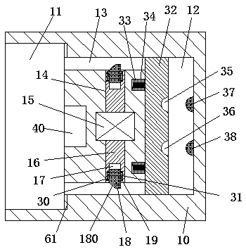
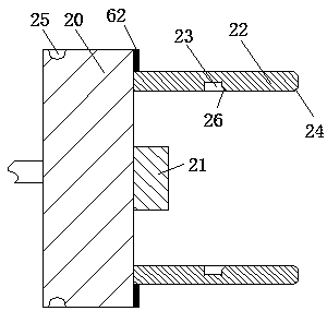
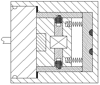
[0022] refer to Figure 1-5 The shown water cup for boiling water includes a cup body 50, a power connection handle 20 fixedly connected to the cup body 50 through a cable, and a power transmission seat 10 mated with the power connection handle 20. 50 is provided with a cup opening 51 on the left end surface, an arm handle 52 on the right end surface, and a cup cover 53 that can be opened and closed at the upper end. Two insertion rods 22 are respectively arranged on the front and rear sides of the insertion post 21, and a locking groove 23 is arranged on the inner end surface of each of the two insertion rods 22, and the two locking grooves 23 ...


PUM


Abstract

The invention discloses a water cup for boiling water. The water cup comprises a cup body, a power connection handle fixedly connected with the cup body and a power transmission seat matched and connected with the power connection handle; a cup mouth is formed in the left end surface of the cup body, an arm hand is arranged on the right end surface, and a cup lid is arranged at the upper end in openable and closeable manners; an inserting column is arranged in the middle on the right end surface of the power connection handle, two inserting rods are respectively and correspondingly arranged atthe positions, on the front side and the rear side of the inserting column, on the right end surface of the power connection handle, a locking slot is formed in each of inside end surfaces in the twoinserting rods, a first guide surface is arranged on the inner side at each of the right end parts in the two locking slots, and a second guide surface is arranged outside each of the right end surfaces in the two inserting rods. The water cup disclosed by the invention has the benefits that the structure is simple, the power supply stability is high, the occurrence of an electric shock accidentwhen the water is boiled is effectively reduced, and the life security of people is guaranteed; the unlocking of the power connection handle is realized under the control of a drive machine, and the unlocking of the power connection handle and the fit connection between the inserting column after ejection and separation and a power connection concave hole can be simultaneously realized; and the power-on and power-off operations of the whole device are simple and convenient.

Description

technical field [0001] The invention relates to the field of water cups, in particular to a water cup for boiling water. Background technique [0002] At present, boiling water cups are widely used. When using the boiling water cups, they need to be powered on first. The cup body is basically powered on by directly inserting the plugs connected to it into the power connection concave holes of the power transmission base, and the power transmission base is connected to the mains. It is always in the power-on state. Although this matching method is relatively simple and convenient to operate, the length of the cable between the post and the cup is different. After the post is inserted into the concave hole of the UMC, there is no other locking device for the post. Locking, when the cable is accidentally kicked and bumped, it will cause the post to be detached from the concave hole of the UMC, resulting in a sudden power failure of the cup, and in severe cases, it will directly...

Claims


Application Information

Patent Timeline
Patent Type & Authority Applications(China)
IPC IPC(8): A47G19/22
CPCA47G19/2288
Inventor 章璐
Owner 广西南宁东能科技有限责任公司
Features
  • Generate Ideas
  • Intellectual Property
  • Life Sciences
  • Materials
  • Tech Scout
  • Unparalleled Data Quality
  • Higher Quality Content
  • 60% Fewer Hallucinations
Learn More