Baijiu production raw material iron removing device
A raw material and liquor technology, applied in the field of iron removal equipment for liquor production raw materials, can solve the problems of limited production efficiency, complex structure, unsatisfactory iron removal effect, etc., and achieve the effect of improving iron removal efficiency and increasing adsorption area
- Summary
- Abstract
- Description
- Claims
- Application Information
AI Technical Summary
Problems solved by technology
Method used
Image

Examples
Embodiment 1
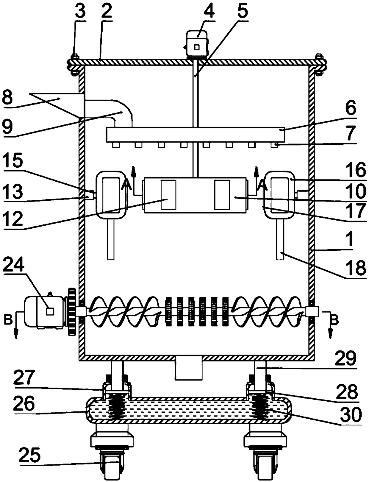
[0025] see Figure 1-4 , a raw material iron removal device with a balance function for liquor production and processing, comprising a housing 1, a cover 2 arranged on the upper part of the housing 1, a bolt assembly 3 for fixedly connecting the top end of the housing 1 to the cover 2 and an installation The first motor 4 on the cover body 2, the inside of the housing 1 is provided with an annular blanking box 6, the bottom of the annular blanking box 6 is fixedly connected with some blanking pipes 7, the side wall of the housing 1 The upper side is provided with a feeding nozzle 8, and the feeding nozzle 8 is connected with the annular lower material box 6 through the connecting pipe 9, and the inside of the housing 1 located at the lower part of the annular lower material box 6 is provided with a rotating ring 10, and the shell The inside of the body 1 is provided with a rotating post 5 fixedly connected to the output end of the first motor 4, the rotating post 5 passes thro...
Embodiment 2
[0036] Different from Embodiment 1, the annular lower material box 6 of this embodiment can rotate together with the rotating ring 10, while the rotating column 5 of Embodiment 1 only passes through the annular lower material box 6, so that the annular lower material box 6 passes through The feeding pipe 7 rotates the material, which improves the contact area between the raw material and the rotating ring 10. The reason is that the circulation path and the circulation area of the rotating material are larger than the vertical discharge.
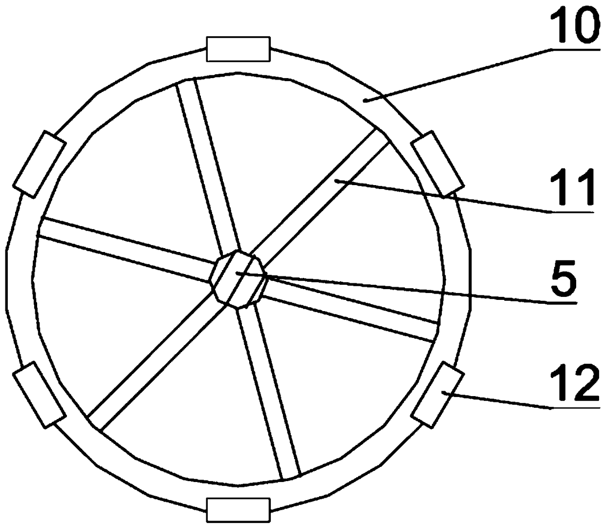
[0037] combine Figure 5As shown, the present embodiment is provided with a connecting sleeve 31 at the center of the annular blanking box 6, and the connecting sleeve 31 and the annular blanking box 6 are fixedly connected by a connecting column 32, and one end of the connecting column 32 is fixed to the outer wall of the connecting sleeve 31. Connect, the other end of connecting column 32 is fixedly connected with the inner wall of ring-s...
Embodiment 3
[0041] The difference from Example 2 is that the combination Image 6 As shown, the connection sleeve 31 of the present embodiment is connected with the rotating column 5 through a transmission mechanism, the transmission mechanism is located in the connection sleeve 31, the transmission mechanism includes a rotating gear 35 and a plurality of transmission gears 36, and the inner wall of the connection sleeve 31 is provided with The ring gear and the rotating gear 35 are provided with column holes for connecting the rotating column 5, and a plurality of transmission gears 36 are arranged between the rotating gear 35 and the connecting sleeve 31, so that the first motor 4 drives the rotating column 5 to rotate, and the rotating gear 35 passes through multiple A transmission gear 36 drives the connecting sleeve 31 to reverse and decelerate to rotate, so that the annular lower material box 6 and the rotating ring 10 rotate in the opposite direction together, and there is also a sp...
PUM
 Abstract
Description
Claims
Application Information
 - R&D
- Intellectual Property
- Life Sciences
- Materials
- Tech Scout
- Unparalleled Data Quality
- Higher Quality Content
- 60% Fewer Hallucinations
Browse by: Latest US Patents, China's latest patents, Technical Efficacy Thesaurus, Application Domain, Technology Topic, Popular Technical Reports.
© 2025 PatSnap. All rights reserved.Legal|Privacy policy|Modern Slavery Act Transparency Statement|Sitemap|About US| Contact US: help@patsnap.com