Complete collector-shoe gear for oil field oil pipe

A full current collector and tubing technology, which is applied in wellbore/well components, earthwork drilling, sealing/isolation, etc., can solve the problems of polluted environment, measurement error, complex structure, etc., achieve low power consumption and avoid leakage liquid, improving stability and compression resistance

Active Publication Date: 2019-02-26
四川省科学城久利电子有限责任公司
View PDF15 Cites 0 Cited by
  • Summary
  • Abstract
  • Description
  • Claims
  • Application Information

AI Technical Summary

Problems solved by technology

They all have their own disadvantages: the umbrella-type current collector adopts the method of opening the umbrella ribs. After the umbrella ribs are opened, they form a polygon and cannot be tightly fitted with the inner wall of the circular oil pipe, resulting in liquid leakage and measurement errors.
Disadvantages of the oil-filled skin bag: complex structure, power consumption during work, and pollution of the environment after the skin bag ruptures, not environmentally friendly

Method used


Image

  • Complete collector-shoe gear for oil field oil pipe
  • Complete collector-shoe gear for oil field oil pipe

Examples


Embodiment 1

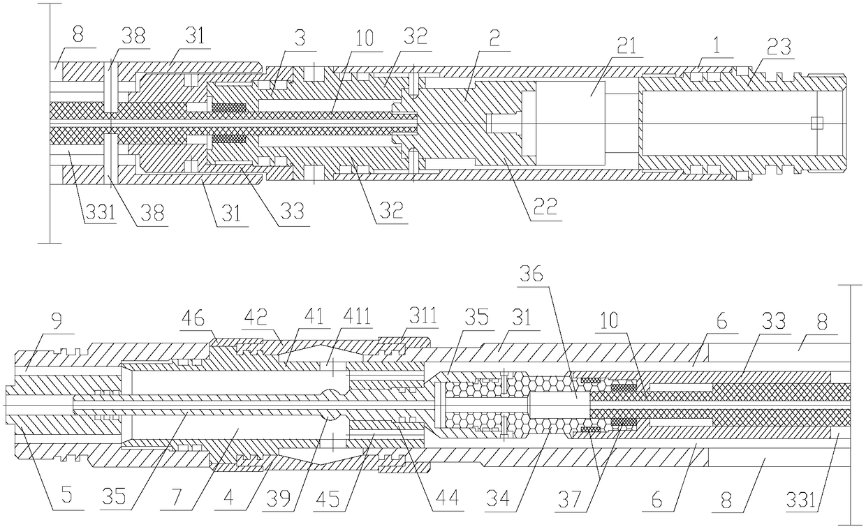
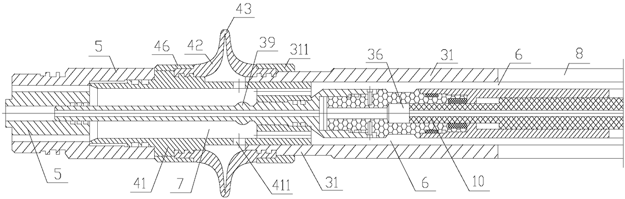
[0029] Such as figure 1 , 2 As shown, the present invention is a full current collector for oilfield tubing, including a casing 1, a pushing mechanism 2, a transmission mechanism 3, a sealing mechanism 4, and a lower outlet joint 5, and the pushing mechanism 2 is arranged in the casing 1 , the push mechanism 2 pushes the transmission mechanism 3, and the transmission mechanism 3 pushes the sealing mechanism 4 to seal off the inner wall of the oil pipe. The transmission mechanism 3 includes a push sleeve 31, and the sealing mechanism 4 includes a sealing cylinder 41 and an elastic sealing ring 42. Cylindrical, one end is fixed on the outer wall of the sealing cylinder 41, the other end is fixed on the outer wall of the tail end of the push sleeve 31, the inner wall of the push sleeve 31 is in sliding contact with the outer wall of the sealing cylinder 41, and the elastic sealing ring 42 is pushed by the push sleeve 31. A circular sealing piece 43 protrudes outward.

[0030] T...

Embodiment 2

[0037] Such as figure 1 , 2 As shown, the present invention is a full current collector for oilfield tubing, including a casing 1, a pushing mechanism 2, a transmission mechanism 3, a sealing mechanism 4, and a lower outlet joint 5, and the pushing mechanism 2 is arranged in the casing 1 , the push mechanism 2 pushes the transmission mechanism 3, and the transmission mechanism 3 pushes the sealing mechanism 4 to seal off the inner wall of the oil pipe. The transmission mechanism 3 includes a push sleeve 31, and the sealing mechanism 4 includes a sealing cylinder 41 and an elastic sealing ring 42. Cylindrical, one end is fixed on the outer wall of the sealing cylinder 41, the other end is fixed on the outer wall of the tail end of the push sleeve 31, the inner wall of the push sleeve 31 is in sliding contact with the outer wall of the sealing cylinder 41, and the elastic sealing ring 42 is pushed by the push sleeve 31. A circular sealing piece 43 protrudes outward.

[0038] T...


PUM


Abstract

The invention discloses a complete collector-shoe gear for an oil field oil pipe. The complete collector-shoe gear comprises a protection cylinder, a pushing mechanism, a transmission mechanism, a sealing mechanism and a liquid outlet lower connector. The pushing mechanism is arranged in the protection cylinder and pushes the transmission mechanism. The transmission mechanism pushes the sealing mechanism to seal the inner wall of the oil pipe. The transmission mechanism comprises a pushing sleeve. The sealing mechanism comprises a sealing cylinder and an elastic seal ring. The elastic seal ring is cylindrical. One end of the elastic seal ring is fixed to the outer wall of the sealing cylinder. The other end of the elastic seal ring is fixed to the outer wall of the tail end of the pushingsleeve. The inner wall of the pushing sleeve slidingly makes contact with the outer wall of the sealing cylinder. The middle of the elastic seal ring is pushed by the pushing cylinder to protrude outwards to form a circular sealing fin. The complete collector-shoe gear is good in sealing performance, high in precision and simple in structure, has lower energy consumption and effectively avoids theliquid leakage phenomenon.

Description

technical field [0001] The invention relates to the field of oil pipe flow collecting devices, in particular to a full flow collector for oil field oil pipes. Background technique [0002] The current collectors for oilfield operations mostly adopt the umbrella type and the bladder oil-filled type. They all have their own disadvantages: the umbrella-type current collector adopts the method of opening the umbrella ribs, which form a polygon after opening, and cannot fit tightly with the inner wall of the circular oil pipe, resulting in liquid leakage and measurement errors. The material for processing the collector umbrella is Oxford cloth, which is easy to be scratched when encountering sharp objects in the oil pipe, resulting in damage to the collector umbrella. The bladder oil-filled current collector is filled with oil, and the piston is used to push the bladder to enlarge and shrink, so as to realize oil pipe collection. Disadvantages of the oil-filled skin bag: comple...

Claims


Application Information

Patent Timeline
Patent Type & Authority Applications(China)
IPC IPC(8): E21B33/08E21B33/10
CPCE21B33/08E21B33/10
Inventor 陈军赵海云涂高鹏赵晓鹏李强夏涛
Owner 四川省科学城久利电子有限责任公司
Why Eureka
Try Eureka