Transmission mechanism of bidirectional automatic gearbox

A technology of automatic transmission and transmission mechanism, which is applied in the field of machinery, can solve problems such as insufficient coordination, poor working stability of the transmission device, and insufficient cooperation between the blocking part and the abutting part, so as to ensure stability, improve stability, The effect of reducing coordination requirements

Active Publication Date: 2019-02-26
屠申富 +1
View PDF12 Cites 4 Cited by
  • Summary
  • Abstract
  • Description
  • Claims
  • Application Information

AI Technical Summary

Problems solved by technology

[0004] However, the abutting part and the blocking part are in a state of relative rotation, that is, the blocking part and the abutting part can only be formed after the blocking part is rotated close to the abutting part, but according to practical experience, two mutually The separate parts need to form abutment after rotation, which requires very high requirements for the angle of rotation and the height position between the parts, which often causes the blocking part and the abutting part to not fit in place or not stable enough during use. , so that the blocking part and the abutting part come into contact and then separate, resulting in poor working stability of the entire transmission

Method used


Image

  • Transmission mechanism of bidirectional automatic gearbox
  • Transmission mechanism of bidirectional automatic gearbox
  • Transmission mechanism of bidirectional automatic gearbox

Examples


Embodiment 1

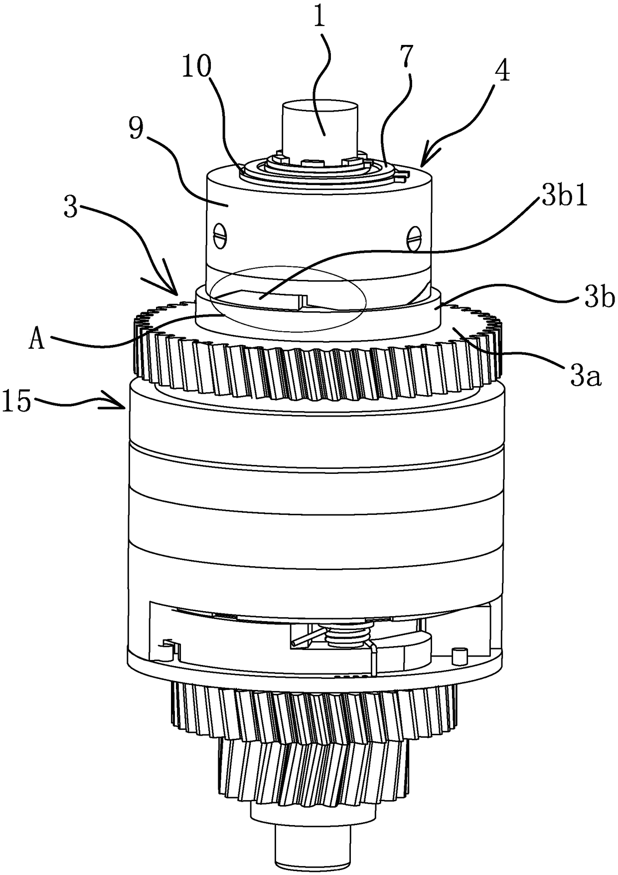
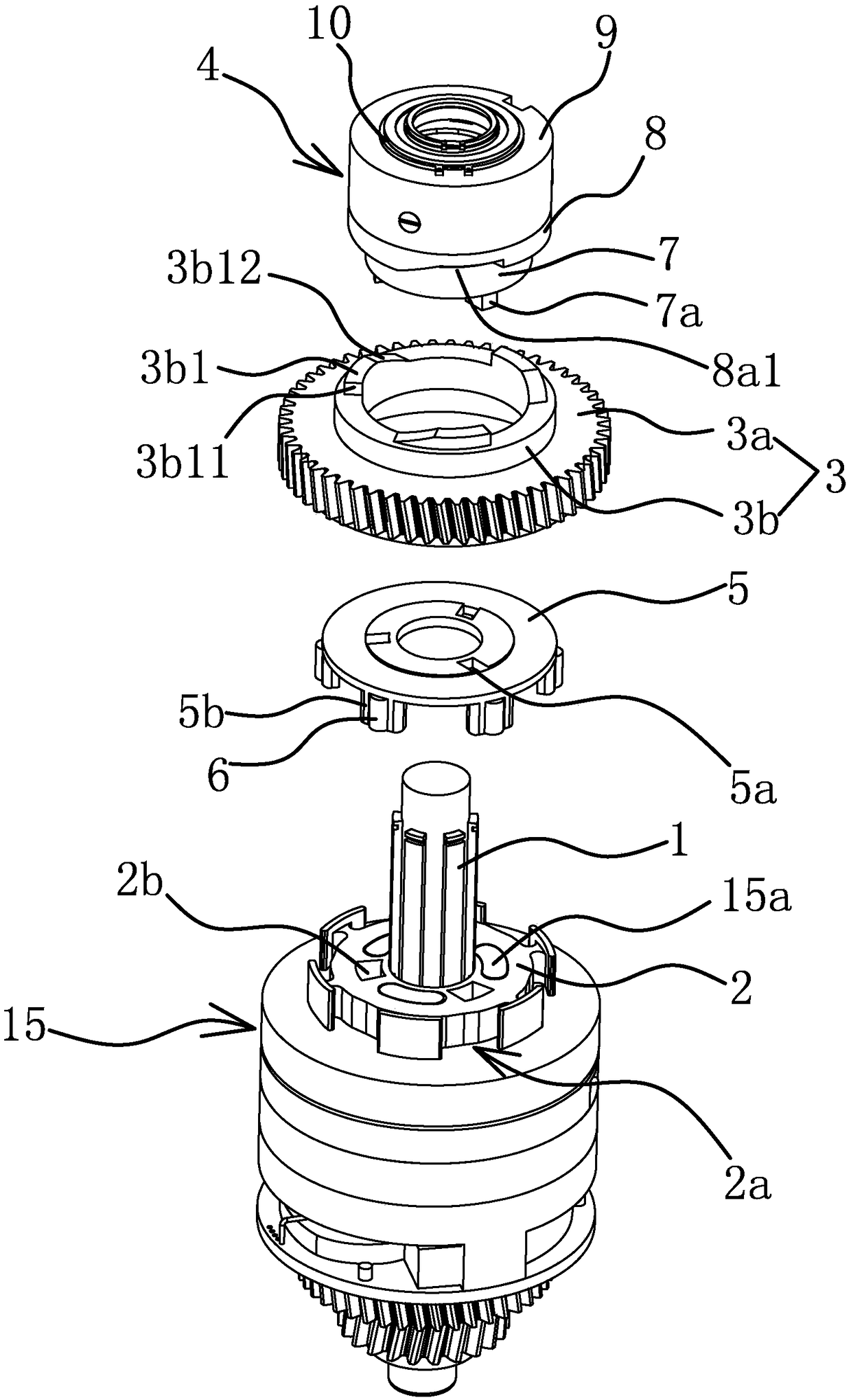
[0046] like figure 1 , figure 2 , image 3 and Figure 11 As shown, a transmission mechanism of a two-way automatic transmission includes a main shaft 1 and an inner ring 2 and a coupling sleeve 4 both sleeved on the main shaft 1. An output gear is fixed on the main shaft 1. The inner ring 2 is in the shape of a ring and the inner ring 2 and the main shaft 1 are fixed in the circumferential direction, and the inner ring 2 is covered with a ring-shaped outer ring 3, and the joint sleeve 4 and the outer ring 3 are provided between the joint sleeve 4 and the outer ring 3. When the outer ring 3 rotates in the direction of making the vehicle reverse The disengagement structure moves away from the outer ring 3, and the main shaft 1 is provided with a large spring 14 that enables the coupling sleeve 4 to approach the outer ring 3.

[0047] like figure 2 As shown, the main shaft 1 is provided with a second gear transmission structure 15 (the specific structure of the second gear...

Embodiment 2

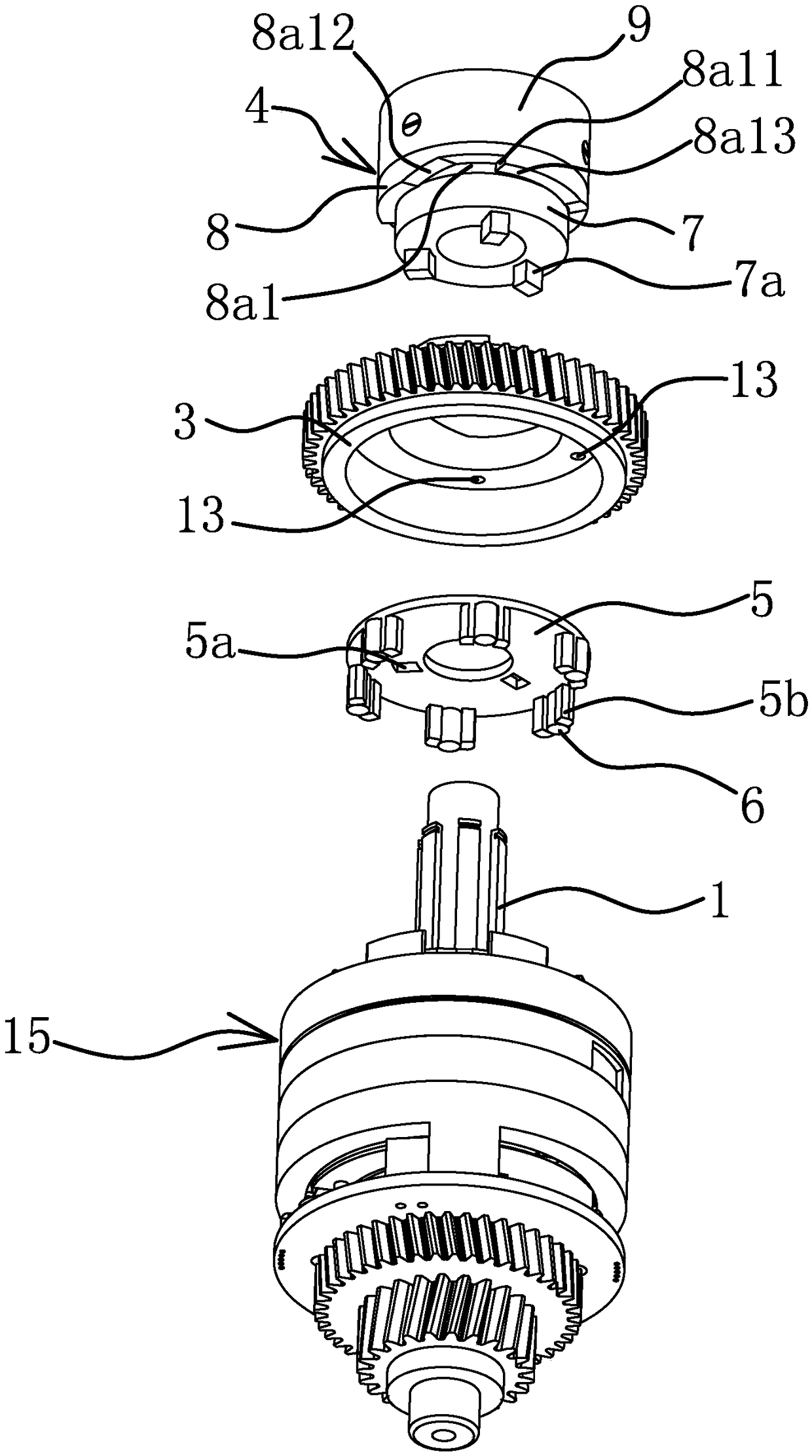
[0063] The structure and principle of this embodiment are basically the same as that of Embodiment 1, the difference is that in this embodiment, the friction structure includes a magnet embedded on the inner side wall of the positioning ring 9, and the ring body 8a of the matching ring 8 is adsorbed by the magnet. On the positioning ring 9. The attraction force of the magnet to the ring body 8a is relatively small, and when the vehicle moves forward or reverses, the magnet has no effect. When the vehicle switches from reverse to forward, since the inclined guide surface 8a13 is provided between the vertical surface 8a11 inside the notch 8a1 and the lower end surface of the annular shoulder 8b, when the outer ring 3 just rotates to the vertical surface on the outside of the block 3b1 When the right angle between the abutment surface 3b11 and the upper end surface of the block 3b1 abuts against the guide surface 8a13, the suction force of the magnet on the mating ring 8 can just...

Embodiment 3

[0065] The structure and principle of this embodiment are basically the same as that of Embodiment 1. The difference is that in this embodiment, the positioning structure includes a number of protrusions arranged on the inner top wall of the outer ring 3 and a number of protrusions arranged on the upper end surface of the coupling plate 5 along the circumferential direction. The shape of the protruding head is the same as that of the groove and the protruding head has elasticity, the number of the protruding heads is less than the number of the grooves, each groove is continuously distributed and there is a circular arc transition between two adjacent grooves.


PUM


Abstract

The invention provides a transmission mechanism of a bidirectional automatic gearbox and belongs to the technical field of machinery. The transmission mechanism solves the problem of low work stability of existing bidirectional automatic gearboxes. The transmission mechanism comprises a main shaft, an inner ring circumferentially fixed to the main shaft, an outer ring sleeving the inner ring and acombining sleeve sleeving the main shaft; a disengagement structure is arranged between the outer ring and the combing sleeve, the outer ring is internally connected with a connecting disc through apositioning structure circumferentially, avoidance segments and first combining segments are arranged on the outer side of the inner ring, first rolling columns are positioned on the connecting disc,and the lower end of the combining sleeve penetrates through the connecting disc and is inserted into the upper end face of the inner ring. When the outer ring rotates in a forward movement directionof a car, the first rolling columns are located at the avoidance segments, and the inner ring and the outer ring slip. When the outer ring rotates in a reverse movement direction of the car, the lowerend of the combing sleeve is retracted into the connecting disc, and the connecting disc drives the first rolling columns to move to the first combining segments and makes the inner ring circumferentially connected with the outer ring. The transmission mechanism has the advantages of being high in work stability, simple in structure and the like.

Description

technical field [0001] The invention belongs to the technical field of machinery and relates to a two-way automatic transmission, in particular to a transmission mechanism of the two-way automatic transmission. Background technique [0002] The traditional two-way automatic variable speed motor realizes the forward or reverse of the electric tricycle through the cooperation of the one-way chuck and the forward one-way device and the reverse one-way device. Scattered distribution, excessive space occupation and other issues. Based on these problems, the applicant has improved the existing technology and applied for a two-way automatic variable speed motor transmission [application number: 201510424829.9]. The space occupied by the entire transmission device is reduced, and the entire structure becomes simpler. However, it also has relatively obvious defects, that is, the separation mechanism related to the forward and reverse cars has extremely high requirements for the ass...

Claims


Application Information

Patent Timeline
Patent Type & Authority Applications(China)
IPC IPC(8): F16H3/087
CPCF16H3/087
Inventor 屠申富屠昌德
Owner 屠申富
Why Eureka
Try Eureka