Automobile instrument fault automatic detection system and method

A technology of automatic detection and automotive instrumentation, which is applied in the direction of test/monitoring control system, vehicle test, general control system, etc. It can solve problems such as long test cycle, low work efficiency, and inability to make accurate judgments on product quality, so as to achieve improvement The effect of test accuracy, test data reliability and shorten test cycle

Inactive Publication Date: 2019-02-26
HUIZHOU DESAY SV AUTOMOTIVE
View PDF10 Cites 11 Cited by
  • Summary
  • Abstract
  • Description
  • Claims
  • Application Information

AI Technical Summary

Problems solved by technology

[0002] When testing automobile faults, it is necessary to simulate the detection time of manufacturing fault codes (DTC) and obtaining fault codes (DTC). This process involves multiple horizontal control and vertical steps, such as controlling power supply voltage, simulating switch status, and signal value of CAN signal Control, time recording and calculation, etc. Traditional manual testing methods are difficult to accurately control the process, cannot obtain accurate test records and data, and cannot provide reliable data sources for subsequent data analysis. unable to make accurate judgments
At the same time, traditional manual testing requires a long test cycle, many repetitive actions, low work efficiency, and large investment in human resources.

Method used


Image

  • Automobile instrument fault automatic detection system and method
  • Automobile instrument fault automatic detection system and method

Examples


Embodiment 1

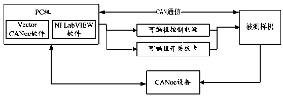
[0034] An automatic detection system for automobile meter faults, such as figure 1 Shown: Including PC, CANoe device, programmable control power supply and programmable switch board, PC is connected to CANoe device, programmable control power supply and programmable switch board respectively, CANoe device, programmable control power supply and programmable switch board The switch boards are respectively connected with the tested prototype; at the same time, the PC is also connected with the tested prototype through CAN communication.

[0035] In this system, the PC has built-in Vector CANoe software or NI LabVIEW software, which is used to control programmable control power supply, programmable switch board and CAN signal to simulate manufacturing fault types through Vector CANoe software or NI LabVIEW software, and through The CANoe device obtains the fault code information and fault occurrence time embodied by the tested prototype; the CANoe device is used to detect the CAN ...

Embodiment 2

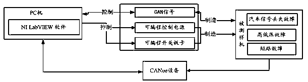
[0041] An automatic detection method based on an automatic detection system for automobile instrument failures, such as figure 2 Shown: including the following steps:

[0042] S10. The PC sends the fault code to the programmable control power supply or programmable switch board through its built-in NI LabVIEW software, so that it can simulate the fault type corresponding to the fault code, and record the fault type and fault generation time.

[0043]This step is specifically, the PC sends the fault codes to the programmable control power supply or the programmable switch board through its built-in NI LabVIEW software, and controls the programmable control power supply or the programmable switch board to simulate the manufacturing and fault codes. Corresponding fault types, at the same time, NI LabVIEW software can also send fault codes to CAN communication and simulate and manufacture car signal loss faults by controlling CAN signals, and record fault types and fault generati...


PUM


Abstract

The invention relates to an automobile instrument fault automatic detection system and method. The system comprises a PC, a CANoe device, a programmable control power supply and a programmable switchboard card. The PC machine is connected with the CANoe device, the programmable control power supply and the programmable switch board card. The CANoe device, the programmable control power supply andthe programmable switch board card are respectively connected with a tested model machine. The PC is used to control the programmable control power supply and the programmable switch board card to simulate and manufacture a fault type, and the fault information embodied by the tested model machine is acquired by the CANoe device. The CANoe device is used to detect the CAN communication and data storage of the tested model machine and used for result judgment. The programmable control power supply is used to simulate a real vehicle power supply. The programmable switch board card is used to simulate a real vehicle rigid line signal and ignition operation. The fault detection system provided by the invention can accurately control detection conditions through a developed NI LabVIEW softwareprogram, can automatically manufacture a fault code, can accurately acquire the fault occurrence time, and shortens a test period.

Description

technical field [0001] The invention relates to the technical field of fault detection of automobile meters, in particular to an automatic detection system and method for faults of automobile meters. Background technique [0002] When testing automobile faults, it is necessary to simulate the detection time of manufacturing fault codes (DTC) and obtaining fault codes (DTC). This process involves multiple horizontal control and vertical steps, such as controlling power supply voltage, simulating switch status, and signal value of CAN signal Control, time recording and calculation, etc. Traditional manual testing methods are difficult to accurately control the process, cannot obtain accurate test records and data, and cannot provide reliable data sources for subsequent data analysis. Can not make accurate judgments. At the same time, traditional manual testing requires a long test cycle, many repetitive actions, low work efficiency, and large investment in human resources. ...

Claims


Application Information

Patent Timeline
Patent Type & Authority Applications(China)
IPC IPC(8): G05B23/02G01M17/007
CPCG01M17/007G05B23/0208
Inventor 钟笔快黄振娟周兰英陈巧燕刘莎莎
Owner HUIZHOU DESAY SV AUTOMOTIVE
Why Eureka
Try Eureka