
Hair dryer flanging roll round machine

A rolling machine and flanging technology, applied in metal processing equipment, feeding devices, manufacturing tools, etc., can solve the problems of inconvenience and manual operation, and achieve the effects of reducing labor costs, improving processing efficiency, and realizing automatic production

Pending Publication Date: 2019-03-01
FOSHAN CITY NANHAI POPULA FAN
View PDF0 Cites 4 Cited by
  • Summary
  • Abstract
  • Description
  • Claims
  • Application Information

AI Technical Summary

Problems solved by technology

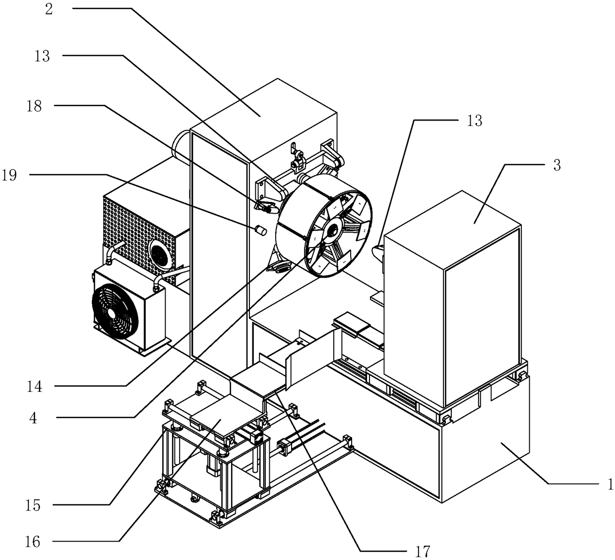
[0002] The forming process of the blower duct is completed by the duct forming machine. The duct forming machine is generally composed of a frame, a forming mechanism, a power system, a control system, a rotating spindle, and an expansion tube installed on it and an expansion and contraction cylinder of the expansion tube. The forming mechanism includes a flanging head and a curling head. The flanging head mainly serves to turn the straight edge into a side with a certain width at 90 degrees, and the curling head rolls the sharp edge into a small circle. And increase the strength of the edge. In order to facilitate the placement of the cylinder, the rotating spindle is generally placed vertically. When working, the expansion tube is first in a contracted state. At this time, the cylinder to be processed is placed on the expansion tube and the expansion and contraction cylinder is activated to expand. The expansion cylinder is fixed on the expansion cylinder, the rotating spindle is started to drive the expansion cylinder and the cylinder to rotate at a certain speed, and then the forming mechanism is started for molding processing. After completion, the forming mechanism returns to the initial state, the spindle stops, and the expansion cylinder returns. Take off the fan cylinder in the contracted state and enter the subsequent processing. Generally, both ends of the fan cylinder are processed. If the shapes of the two ends are consistent, just turn around and process. If the shapes of the two ends are different, they must be processed on another machine. Loading and unloading It is extremely inconvenient to manually operate materials and change the processing position of the blower

Method used


Image

  • Hair dryer flanging roll round machine
  • Hair dryer flanging roll round machine
  • Hair dryer flanging roll round machine

Examples


Embodiment Construction

[0019] The concept, specific structure and technical effects of the present application will be clearly and completely described below in conjunction with the embodiments and drawings, so as to fully understand the purpose, features and effects of the present application. Apparently, the described embodiments are only some of the embodiments of the present application, not all of them. Based on the embodiments of the present application, other embodiments obtained by those skilled in the art without creative efforts belong to The protection scope of this application. In addition, all the connection / connection relationships mentioned in this article do not refer to the direct connection of components, but mean that a better connection structure can be formed by adding or reducing connection accessories according to specific implementation conditions. The various technical features in the invention can be combined interactively on the premise of not conflicting with each other. ...


PUM


Abstract

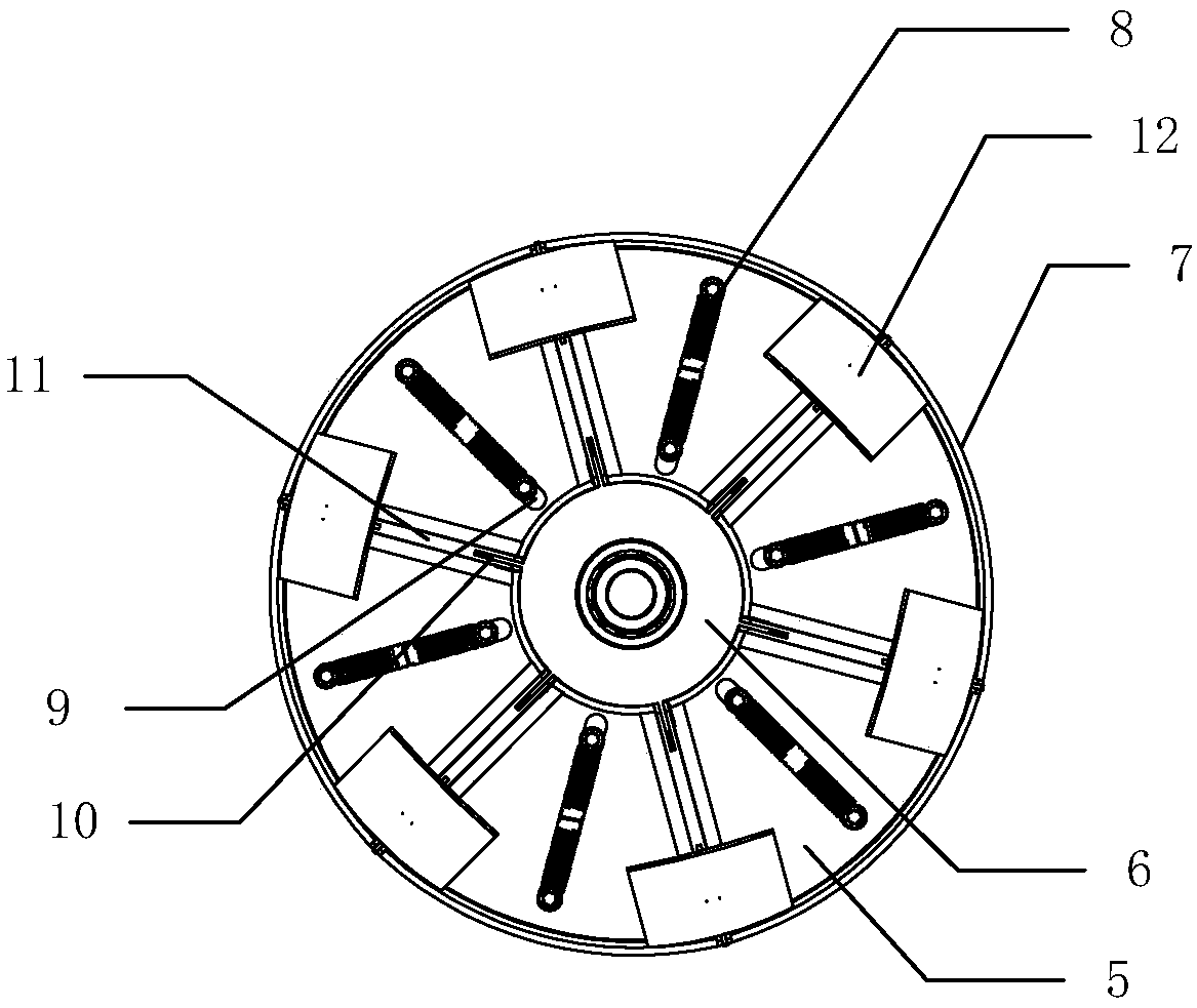
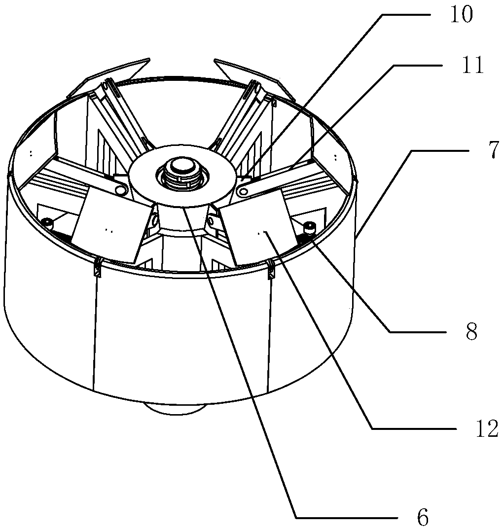
The invention discloses a hair dryer flanging roll round machine. The hair dryer flanging roll round machine comprises a machine frame, a fixed end is arranged on one side of the machine frame, and amovable end is connected to the other side of the machine frame in a transmission mode through a linear guide. The movable end moves back and forth in the direction which is close to the fixed end, afeeding mechanism is arranged on one side of the fixed end, an expansion container is arranged on the side surface, close to the movable end, of the fixed end, a first flanging roll round mechanism isarranged on one side of the expansion container, a second flanging roll round mechanism is arranged on the side surface, close to the fixed end, of the movable end, and the expansion container is intransmission connection with the fixed end through a drive mechanism. According to the hair dryer flanging roll round machine, automatic machining and production of the flanging and roll round of a hair dryer is realized, positioning and clamping of the hair dryer is more convenient, two ends of the hair dryer are machined simultaneously, and the machining efficiency is further improved.

Description

technical field [0001] The present application relates to a round rolling machine, in particular to an air cylinder flanging round rolling machine. Background technique [0002] The forming process of the blower duct is completed by the duct forming machine. The duct forming machine is generally composed of a frame, a forming mechanism, a power system, a control system, a rotating spindle, and an expansion tube installed on it and an expansion and contraction cylinder of the expansion tube. The forming mechanism includes a flanging head and a curling head. The flanging head mainly serves to turn the straight edge into a side with a certain width at 90 degrees, and the curling head rolls the sharp edge into a small circle. And increase the strength of the edge. In order to facilitate the placement of the cylinder, the rotating spindle is generally placed vertically. When working, the expansion tube is first in a contracted state. At this time, the cylinder to be processed is ...

Claims


Application Information

Patent Timeline
IPC IPC(8): B21D19/14B21D43/00
CPCB21D19/14B21D43/003
Inventor 唐秀文黄建军
Owner FOSHAN CITY NANHAI POPULA FAN
Learn More