Brazing method for water-cooling plates

A brazing method and water-cooled plate technology, applied in welding equipment, auxiliary devices, metal processing equipment, etc., can solve the problems that the flatness of brazing fixtures cannot be guaranteed, affect the surface flatness of the water-cooled plate, and affect the surface finish of the water-cooled plate. Achieve the effects of shortening the time of clamping, facilitating clamping and positioning, and improving efficiency

Inactive Publication Date: 2019-03-01
扬州嘉和新能源科技有限公司
View PDF5 Cites 4 Cited by
  • Summary
  • Abstract
  • Description
  • Claims
  • Application Information

AI Technical Summary

Problems solved by technology

[0002] At present, when brazing the water-cooled plate, the brazing fixture is usually used to clamp the water-cooled; by placing the water-cooled plate on the brazing fixture, and then using a brazing furnace to braze the water-cooled plate; the existing brazing fixture Most of them are produced by stainless steel tailor welding, and the flatness of the brazing fixture cannot be guaranteed, which will affect the

Method used


Image

  • Brazing method for water-cooling plates
  • Brazing method for water-cooling plates
  • Brazing method for water-cooling plates

Examples


Example Embodiment

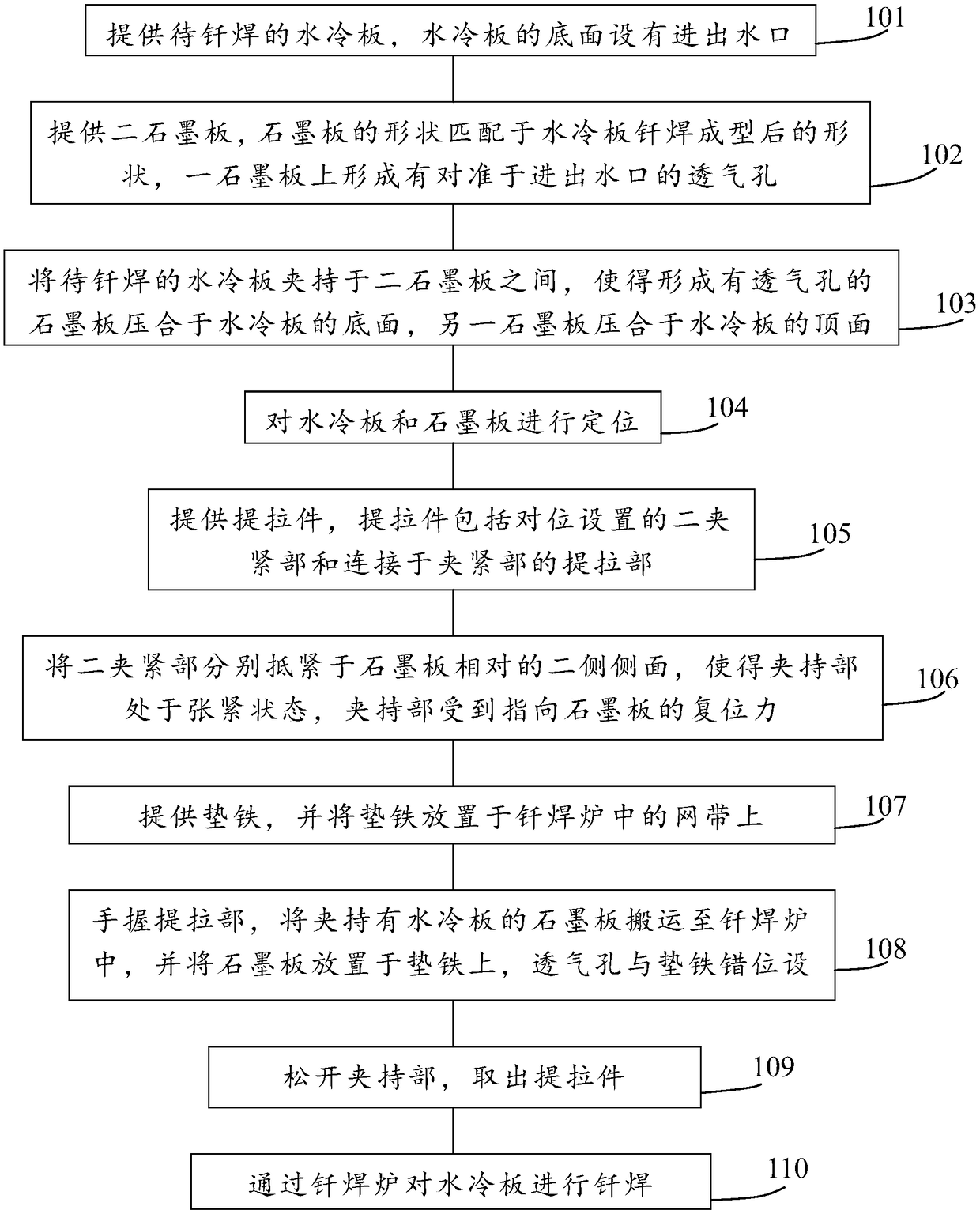
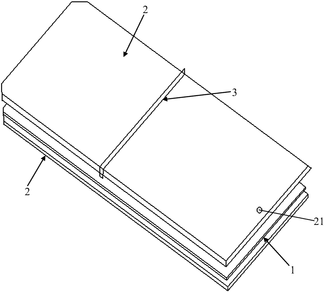
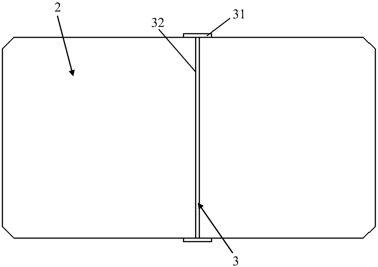
[0050] Embodiment 1: In the lifting member 3, the clamping portion 31 is a resilient member, and the lifting portion 32 is a connecting rod connected to the resilient member by welding. In this embodiment, by supporting the two resilient members on opposite sides of the graphite plate 2, the resilient members are in tension, and the restoring force of the resilient members is used to clamp the graphite plate 2, and then use The lifting member 3 completes the conveyance of the graphite plate 2 holding the water-cooled plate 1. Specifically, (1) the resilient member is T-shaped; (2) the lifting member 3 is a component with a constant cross-section, with a cross-sectional diameter of 6 mm.

Example Embodiment

[0051] Embodiment 2: The clamping part 31 is a claw, and the lifting part 32 is a pull ring fixed to the claw. The two claws are pivotally connected by a pivot, and a torsion spring is sleeved in the pivot connection. The first end of the torsion spring The second end of the torsion spring abuts or is connected to another claw. In this embodiment, by supporting the two claws on opposite sides of the graphite plate 2 respectively (the torsion spring is in a tensioned state and receives a resetting force), the graphite plate 2 is clamped by the resetting force of the torsion spring. , The structure is simple and easy to operate.

[0052] In the present invention, the stainless steel brazing fixture in the prior art is replaced by two graphite plates 2 to simplify the structure of the brazing fixture, shorten the time for installing the brazing fixture, and further improve the production efficiency of the water-cooled plate 1.

[0053] In the present invention, the length of the braz...


PUM

PropertyMeasurementUnit
Flatnessaaaaaaaaaa
Thicknessaaaaaaaaaa

Abstract

The invention provides a brazing method for water-cooling plates. The brazing method comprises the following steps: providing water-cooling plates to be brazed, providing two graphite plates, and putting the water-cooling plates between the two graphite plates; locating the water-cooling plates and the graphite plates; providing a lifting element, specifically, the lifting element comprises two clamping parts which are set oppositely and a lifting part which is connected with the clamping parts; making the two clamping parts correspondingly abut against the two opposite sides of the graphite plates so that the clamping parts can be in tension state and bear reset force which points to the graphite plates; providing an iron cushion, placing the iron cushion on a net belt in a brazing furnace, holding the lifting part with hands, and carrying the graphite plates which clamp the water-cooling plates to the brazing furnace; and placing the graphite plates on the iron cushion, releasing theclamping parts, taking out the lifting element, and brazing the water-cooling plates by the brazing furnace. The brazing method of the invention can improve the brazing quality and production efficiency of the water-cooling plates.

Description

technical field [0001] The invention relates to the field of brazing of water-cooled plates, in particular to a brazing method of water-cooled plates. Background technique [0002] At present, when brazing the water-cooled plate, the brazing fixture is usually used to clamp the water-cooled; by placing the water-cooled plate on the brazing fixture, and then using a brazing furnace to braze the water-cooled plate; the existing brazing fixture Most of them are produced by stainless steel tailor welding, and the flatness of the brazing fixture cannot be guaranteed, which will affect the flatness of the surface of the water-cooled plate after brazing. At the same time, the use of stainless steel brazing fixture will cause the surface of the water-cooled plate to appear The black oxide layer seriously affects the smoothness of the surface of the water-cooled plate; therefore, a brazing method for the water-cooled plate is designed to improve the quality of the final brazing of th...

Claims


Application Information

Patent Timeline
IPC IPC(8): B23K1/008B23K3/08
CPCB23K1/008B23K3/087
Inventor 李宝民杜郑马树扬
Owner 扬州嘉和新能源科技有限公司
Why Eureka
Try Eureka