Part automatic material collecting device in plasma flame cutting platform water tank

A technology of flame cutting and automatic material collection, which is applied in the direction of plasma welding equipment, gas flame welding equipment, manufacturing tools, etc., can solve the problems of difficult and cumbersome parts collection, avoid manual participation in the work of collecting parts, improve collection efficiency, and improve The effect of receiving efficiency

Inactive Publication Date: 2019-03-01
CHINA FIRST METALLURGICAL GROUP +1
3 Cites 2 Cited by

AI-Extracted Technical Summary

Problems solved by technology

[0005] In view of the above technical problems, the purpose of the present invention is to provide an automatic receiving device for parts in the water tank of the p...

Abstract

The invention belongs to the field of plasma flame cutting equipment, in particular to a part automatic material collecting device in a plasma flame cutting platform water tank. The device comprises abelt conveyor, wherein a water tank is located between an upper-layer conveying belt and a lower-layer conveying belt of the belt conveyor, the upper-layer conveying belt of the belt conveyor is pressed down into the water surface in the water tank through first downward pressing rolling wheels. According to the device, the belt conveyor is additionally arranged at the water tank, the parts, which fall into the water tank, from gaps of platform plate strips are automatically conveyed into a material collecting hopper through the conveying belts, and the problem that the parts in the water tank below the numerical control plasma flame cutting platform is difficult to collect is solved; and the material collecting efficiency of the parts after material blanking and cutting is improved, meanwhile, due to the buffering effect of a water body, the conveying belts cannot be damaged due to the falling impact of the parts.

Application Domain

Plasma welding apparatusGas flame welding apparatus

Technology Topic

EngineeringWater tanks +4

Image

  • Part automatic material collecting device in plasma flame cutting platform water tank
  • Part automatic material collecting device in plasma flame cutting platform water tank
  • Part automatic material collecting device in plasma flame cutting platform water tank

Examples

  • Experimental program(1)

Example Embodiment

[0027] In order to better understand the present invention, the technical solutions of the present invention will be further described below in conjunction with embodiments and drawings (such as Figure 1-4 Shown).
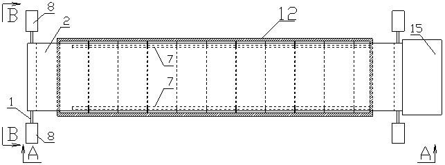
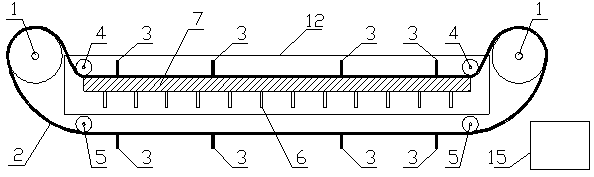
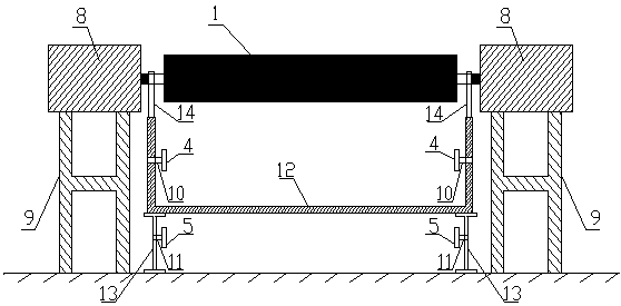
[0028] An automatic receiving device for parts in a water tank of a plasma flame cutting platform includes a belt conveyor. The water tank 12 is located between the upper and lower conveyor belts 2 of the belt conveyor. The upper conveyor belt 2 of the belt conveyor passes through a first lower roller 4 Press down to below the water surface in the sink 12. It also includes a collecting hopper 15 located below the tail of the belt conveyor for collecting parts.
[0029] The belt conveyor includes a pair of main drive rollers 1 and a transmission belt 2, the transmission belt 2 is looped around a pair of main drive rollers 1, and the pair of main drive rollers 1 are respectively located on the front and rear sides of the tank 12 , The two ends of the main drive roller 1 are erected above the water tank 12 through the bearing seat 14; the two ends of each main drive roller 1 are respectively connected with a drive motor 8 for driving the main drive roller 1 to rotate, each The driving motors 8 are all mounted on the bottom surface through a motor support 9 which is made of section steel. The conveyor belt 2 is a stainless steel chip removal chain plate. The outer surface of the conveyor belt 2 is uniformly provided with more than one baffle 3 along the length direction, preferably more than eight. The bottom of the baffle 3 is provided with a number of dense drainage holes. The width of the baffle 3 is the same as that of the conveyor belt 2. It is best to just not touch the first pressing roller 4 to match.
[0030] A supporting platform for supporting the conveyor belt 2 is provided in the water tank 12. The support platform includes a plurality of longitudinal supports 7 arranged in parallel along the direction of movement of the conveyor belt 2, and the plurality of longitudinal supports 7 are fixedly connected by a plurality of transverse supports 6; the transverse supports 6 are perpendicular to the longitudinal supports 7 and are located in the longitudinal direction. Below the support 7, the lateral support 6 is welded to the bottom of the sink 12.
[0031] A plurality of first down-pressing rollers 4 are respectively provided on the left and right side walls inside the water tank 12, and the first down-pressing rollers 4 are fixedly installed on the side walls through the first bearings 10, and the front and rear ends of the side walls Each has a first pressing roller 4, and the plurality of first pressing rollers 4 are pressed on the left and right edges of the conveyor belt 2.
[0032] The bottom of the water tank 12 is provided with two water tank supports 13, which are I-steel brackets and have the same length as the water tank 12. The two water tank supports 13 are respectively located on the left and right sides of the bottom of the water tank 12 for raising and erecting the water tank 12, and the lower transmission belt 2 of the belt conveyor is located between the two water tank supports 13. The inner side of each sink bracket 13 is provided with a plurality of second pressing rollers 5, the second pressing rollers 5 are fixedly installed on the inner side of the sink bracket 13 through the second bearing 11. The front and rear ends of the sink bracket 13 are respectively A second pressing roller 5 is provided, and the plurality of second pressing rollers 5 are used to press the lower conveyor belt 2 down.
[0033] The working principle and working process of the present invention are as follows:
[0034] 1) The conveyor belt 2 made of stainless steel chip removal chain plate is looped and linked on the two main drive rollers 1, the four first down rollers 4, and the four second down rollers 5 to form a closed.
[0035] 2) The two main drive rollers 1 are higher than the water surface of the water tank 12. The conveyor belt 2 will be lifted out of the water surface of the water tank 12 when it runs to the main drive roller 1.
[0036] 3) The upper surface of the first pressing roller 4 is lower than the water surface of the water tank 12, and the conveyor belt 2 located at the first pressing roller 4 will also enter below the water surface of the water tank 12 when it is transferred to this area.
[0037] 4) The water tank bracket 13 raises the water tank 12 and raises the bottom of the water tank 12 above the water tank. The second pressing roller 5 is fixed on the water tank bracket 13 through the second bearing 11, and the conveyor belt 2 located at the second pressing roller 5 will pass under the water tank 12.
[0038] 5) Through the above scheme, the conveyor belt 2 forms a concave closed loop that passes through the inside of the water body of the water tank 12 and the space under the water tank.
[0039] 6) When the dimensions of the cut parts are smaller than the gap between the platform slats, the parts will fall into the lower tank 12 through the gap between the slats and be taken by the conveyor belt 2 of the underwater part.
[0040] 7) Turn on the driving motor 8 to drive the main drive roller 1 to rotate, and then drive the transmission belt 2 and the parts carried on it to the tail, and lift the water surface of the water tank 12 through the main drive roller 1 at the tail.
[0041] 8) During the lifting process, the parts are blocked from sliding down by the stopper 3 welded on the conveyor belt 2, and at the same time, the lifted water is discharged into the sink 12 through the dense drainage holes at the lower part of the stopper 3 to realize automatic separation of the parts and water .
[0042] 9) After the parts are transported through the upper part of the main drive roller 1, they fall down and fall into the hopper 15 placed under the tail of the conveyor belt 2, so as to realize the automatic collection of underwater parts.
[0043] The above description is only the application examples of the present invention, and of course it cannot be used to limit the scope of rights of the present invention. Therefore, equivalent changes made according to the scope of patent application of the present invention still belong to the protection scope of the present invention.

PUM

no PUM

Description & Claims & Application Information

We can also present the details of the Description, Claims and Application information to help users get a comprehensive understanding of the technical details of the patent, such as background art, summary of invention, brief description of drawings, description of embodiments, and other original content. On the other hand, users can also determine the specific scope of protection of the technology through the list of claims; as well as understand the changes in the life cycle of the technology with the presentation of the patent timeline. Login to view more.

Similar technology patents

Photovoltaic power generation equipment with adjustable angles and flexible installation

InactiveCN113162533AFlexible installationImprove receiving efficiency
Owner:温州黎肯电子商务股份有限公司

Automatic material receiving device

InactiveCN107160639AImprove receiving efficiencyImprove packaging efficiency
Owner:TIANJIN HONGXIANG PLASTIC PROD

Data receiving method and device

ActiveCN110278052AGuaranteed real-timeImprove receiving efficiency
Owner:DATANG MOBILE COMM EQUIP CO LTD

Novel solar street lamp

PendingCN112555747AGood collection of sunlightImprove receiving efficiency
Owner:淮南市新光源特种照明器材有限公司

Tracking type photovoltaic power generation device with cleaning function

InactiveCN111262515ARealize the tracking effectImprove receiving efficiency
Owner:宁波市路棠电子科技有限公司

Classification and recommendation of technical efficacy words

  • Improve receiving efficiency
  • good efficiency

Double-layer grid mesh spherical secondary electronic collector

ActiveCN109100380AImprove receiving efficiencyshield interference
Owner:INST OF FLUID PHYSICS CHINA ACAD OF ENG PHYSICS

Vibration-free collecting device for cylindrical batteries

PendingCN107826726ASave receiving timeImprove receiving efficiency
Owner:SHENZHEN ZYE TECH LTD

LED Lamp assembly apparatus

InactiveCN108890254AImprove receiving efficiencyImprove assembly efficiency
Owner:韦美芬

Photovoltaic power generation equipment with adjustable angles and flexible installation

InactiveCN113162533AFlexible installationImprove receiving efficiency
Owner:温州黎肯电子商务股份有限公司

Radio frequency textile drying machine

InactiveUS20070045307A1reduce maintenance costgood efficiency
Owner:FALMER INVESTMENTS LTD

Switching between bit-streams in video transmission

ActiveUS7706447B2good efficiencyenough adaptability
Owner:NOKIA TECHNOLOGLES OY

Sealed battery and manufacturing method therefor

ActiveCN101335339AReactive current reductiongood efficiency
Owner:SANYO ELECTRIC CO LTD
Why Eureka
Try Eureka