
Electric tool

A technology for power tools and safe work, applied in the direction of manufacturing tools, portable mobile devices, etc., which can solve problems such as unnecessary accidents and unexpected startup of power tools.

Pending Publication Date: 2019-03-01
POSITEC POWER TOOLS (SUZHOU) CO LTD
View PDF8 Cites 0 Cited by
  • Summary
  • Abstract
  • Description
  • Claims
  • Application Information

AI Technical Summary

Problems solved by technology

When the stop and emergency stop buttons are pressed, the flip cover next to the stop and emergency stop buttons is opened by external force. There are function keys for adjusting the data of the power tool under the flip cover. The parameters of the power tool can be adjusted through the function keys. Go to the next step. When the cover is opened, the power tool can also be restarted. If the cover is opened and the function button is misoperated, that is, the function is still activated when the cover is opened. Adjusting the button leads to the adjustment of the parameters of the electric tool, which makes the electric tool start unexpectedly, which may cause unnecessary accidents and pose a safety hazard

Method used


Image

  • Electric tool
  • Electric tool

Examples


Embodiment Construction

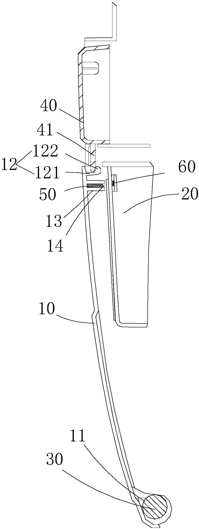
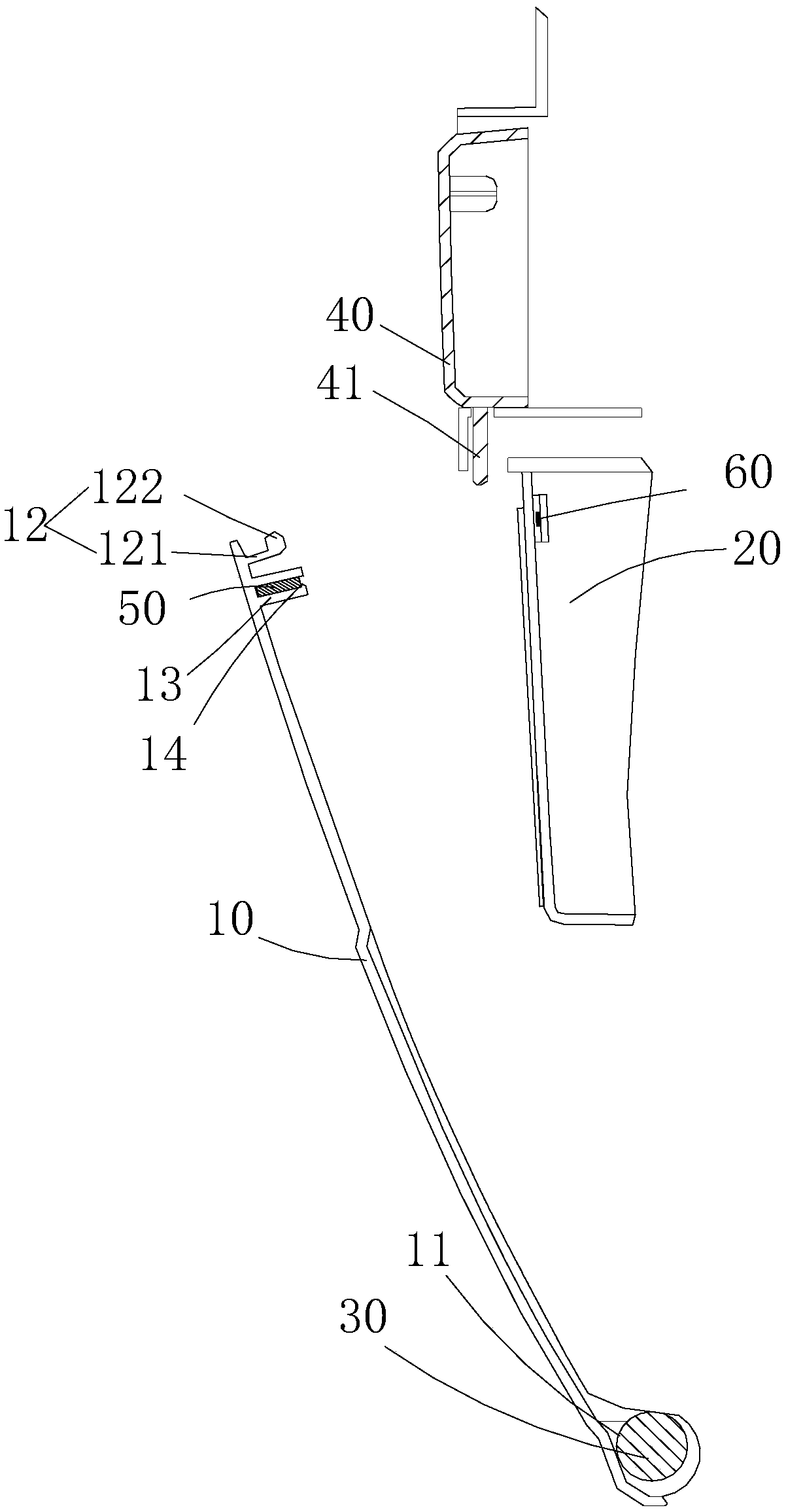
[0023] Please refer to figure 1 and figure 2 As shown, the power tool in this embodiment includes a flip cover 10, a fixing member 20 located below the flip cover 10, a rotating shaft 30 for installing the flip cover 10, a button 40 that can stop the power tool, and a button 40 installed on the flip cover 10 and the fixing member respectively. A pair of sensing elements on 20. A pair of sensing elements may be collectively referred to as a sensing assembly. In this embodiment, the sensing element includes a magnetic element 50 and a sensor 60 . In this embodiment, the magnetic member 50 is a magnet. In other embodiments, the button 40 is not limited to the stop function of the power tool, and can be any button for opening the flip cover 10 .

[0024] The flip cover 10 is a plate-like structure extending longitudinally, and its surface has a certain curvature. The flip cover 10 is provided with a rotation hole 11 at its rear end, the rotation shaft 30 passes through the r...


PUM


Abstract

The invention discloses an electric tool. The electric tool comprises a flip cover, a fixing part located below the flip cover and a rotating shaft, wherein the rotating shaft is used for installing the flip cover; and the electric tool further comprises a pair of sensing elements installed on the flip cover and on the fixing part correspondingly. When the flip cover is closed, the sensing elements located on the flip cover and the fixing part sense each other, so that a command indicating safety working can be carried out is provided for the electric tool, when the flip cover is turned up, the sensing elements located on the flip cover and the fixing part sense each other, and a command indicating non-safety working can be provided for the electric tool, therefore, mutual sensing sensingelements are arranged on the flip cover and the fixing part correspondingly, so that the electric tool is caused to work only when the flip cover is closed, and an accident phenomenon caused by the fact that a parameter button, a function key or a starting button on the electric tool are carelessly touched is avoided.

Description

[0001] This application is a divisional application of the Chinese invention patent application with the name "Electric Tool" and application number 201310348990.3 filed by the applicant on August 12, 2013. technical field [0002] The invention relates to an electric tool. Background technique [0003] In the prior art, any electric tool such as a cutting machine or a lawnmower has a stop button, or an emergency stop function device for handling an emergency, and an emergency stop button is generally provided on the electric tool. When the stop and emergency stop buttons are pressed, the electric tool will stop working immediately, which is a good way to prevent accidents from happening. When the stop and emergency stop buttons are pressed, the flip cover next to the stop and emergency stop buttons is opened by external force. There are function keys for adjusting the data of the power tool under the flip cover. The parameters of the power tool can be adjusted through the f...

Claims


Application Information

Patent Timeline
Patent Type & Authority Applications(China)
IPC IPC(8): B25F5/00
CPCB25F5/00
Inventor 杨晓岗杜江
Owner POSITEC POWER TOOLS (SUZHOU) CO LTD
Learn More