Electric power overhaul tool box
A technology of electric power maintenance and toolbox, which is applied in the direction of manufacturing tools and tool storage devices, etc., which can solve problems such as time-consuming and laborious placement of various tools, inconvenient power maintenance, etc., and achieve the effect of convenient construction
- Summary
- Abstract
- Description
- Claims
- Application Information
AI Technical Summary
Problems solved by technology
Method used
Image
Examples
Embodiment 1
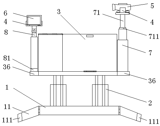
[0023] like Figure 1-2 As shown, the present invention provides a power maintenance tool box, including a base plate 1, a first telescopic member 2, a storage box 3, a clamping member 4, a second telescopic member 7, a first rotating shaft 71 and a second rotating shaft 8; the base plate 1 is connected to the bottom of the storage box 3 through the first telescopic piece 2; the two sides of the bottom of the storage box 3 are respectively provided with an observation connecting plate 36; the second telescopic piece 7 is installed on one of the observation connecting plate 36, and the second telescopic piece The movable end of 7 is connected with the first rotating shaft 71 through the first rotating disk 711, and the free end of the first rotating shaft 71 is installed with the holder 4; the second rotating shaft 8 is installed on the other observation connecting plate 36, and the second rotating shaft 8 passes through the second The turntable 81 is connected with the second ...
Embodiment 2
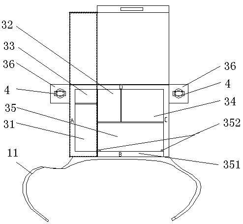
[0029] Considering the space composition, the convenience of storage and the preparations required before power maintenance, the storage box 3 is as follows: figure 2 As shown, an infrared camera storage compartment 31 , a display screen storage compartment 32 , a cable storage compartment 33 , a first tool storage compartment 34 and a second tool storage compartment 35 are arranged therein.
[0030] like figure 2 As shown, the width of the connecting line storage compartment 33 and the infrared camera storage compartment 31 is the same, and the connection line storage compartment 33 and the infrared camera storage compartment 31 are aligned and arranged on the A side of the storage box 3. The instrument storage compartment 31 is aligned with the second tool storage compartment 35, the second tool storage compartment 35 is disposed on the B side adjacent to the A side, and the second tool storage compartment 35 is aligned with the first tool storage compartment 34 , the fir...
Embodiment 3
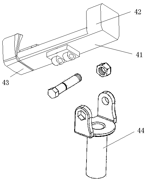
[0037] like image 3 As shown, the clip 4 is an elastically telescopic clip 4 . The clamping part 4 includes a base plate 41, a right clamping plate 42 and a left clamping arm 43. The right clamping plate 42 is fixedly mounted on one end of the base plate 41, and the left clamping arm 43 is movably connected with the base plate 41. This structure is a prior art, not much here Do repeat.
[0038] In addition, the bottom of the base plate 41 is provided with a connecting cylinder, and the clamping member 4 is connected with the first rotating shaft 71 through the cooperation of the connecting cylinder, the connecting head 44 and the fastener. The camera angle of camera 5 is adjusted.
PUM
 Abstract
Description
Claims
Application Information
 - R&D
- Intellectual Property
- Life Sciences
- Materials
- Tech Scout
- Unparalleled Data Quality
- Higher Quality Content
- 60% Fewer Hallucinations
Browse by: Latest US Patents, China's latest patents, Technical Efficacy Thesaurus, Application Domain, Technology Topic, Popular Technical Reports.
© 2025 PatSnap. All rights reserved.Legal|Privacy policy|Modern Slavery Act Transparency Statement|Sitemap|About US| Contact US: help@patsnap.com


