Mold clamping mechanism of two-plate injection molding machine

A mold clamping mechanism and injection molding machine technology, applied in the field of injection molding machines, can solve the problems of large mold clamping cylinder, lower production efficiency, increase injection time, etc., achieve the effect of shortening injection molding cycle, improving production efficiency, and high degree of linkage

Pending Publication Date: 2019-03-01
HAITIAN PLASTICS MACHINERY GRP
View PDF0 Cites 2 Cited by
  • Summary
  • Abstract
  • Description
  • Claims
  • Application Information

AI Technical Summary

Problems solved by technology

[0003] The mold clamping mechanism of the existing two-platen injection molding machine has the following problems: the volume of the existing mold clamping cylinder is much larger than that of the mold moving cylinder. To achieve the next smooth closing, the position of the clamping piston rod is adjusted by feeding oil into the rod chamber of the clamping cylinder. However, due to the large volume of the clamping cylinder, the full flow support of the hydraulic system is required. Compared with the speed, the speed is far behind, which leads to the inability to link with the mold transfer cylinder. In the entire injection molding cycle, the position of the clamping piston rod must be adjusted after the mold is clamped in place, which increases the injection molding time and greatly reduces the production efficiency.

Method used


Image

  • Mold clamping mechanism of two-plate injection molding machine
  • Mold clamping mechanism of two-plate injection molding machine
  • Mold clamping mechanism of two-plate injection molding machine

Examples


Embodiment

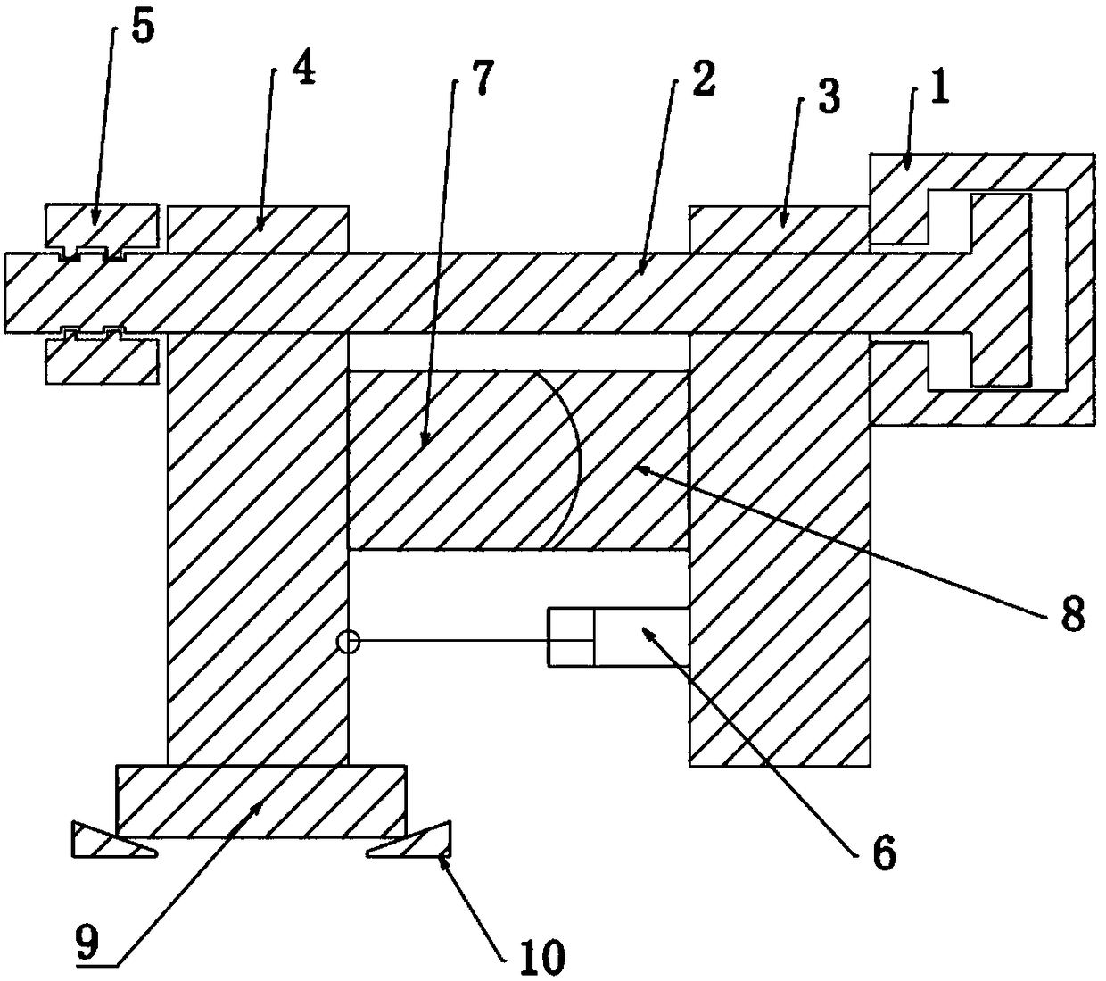
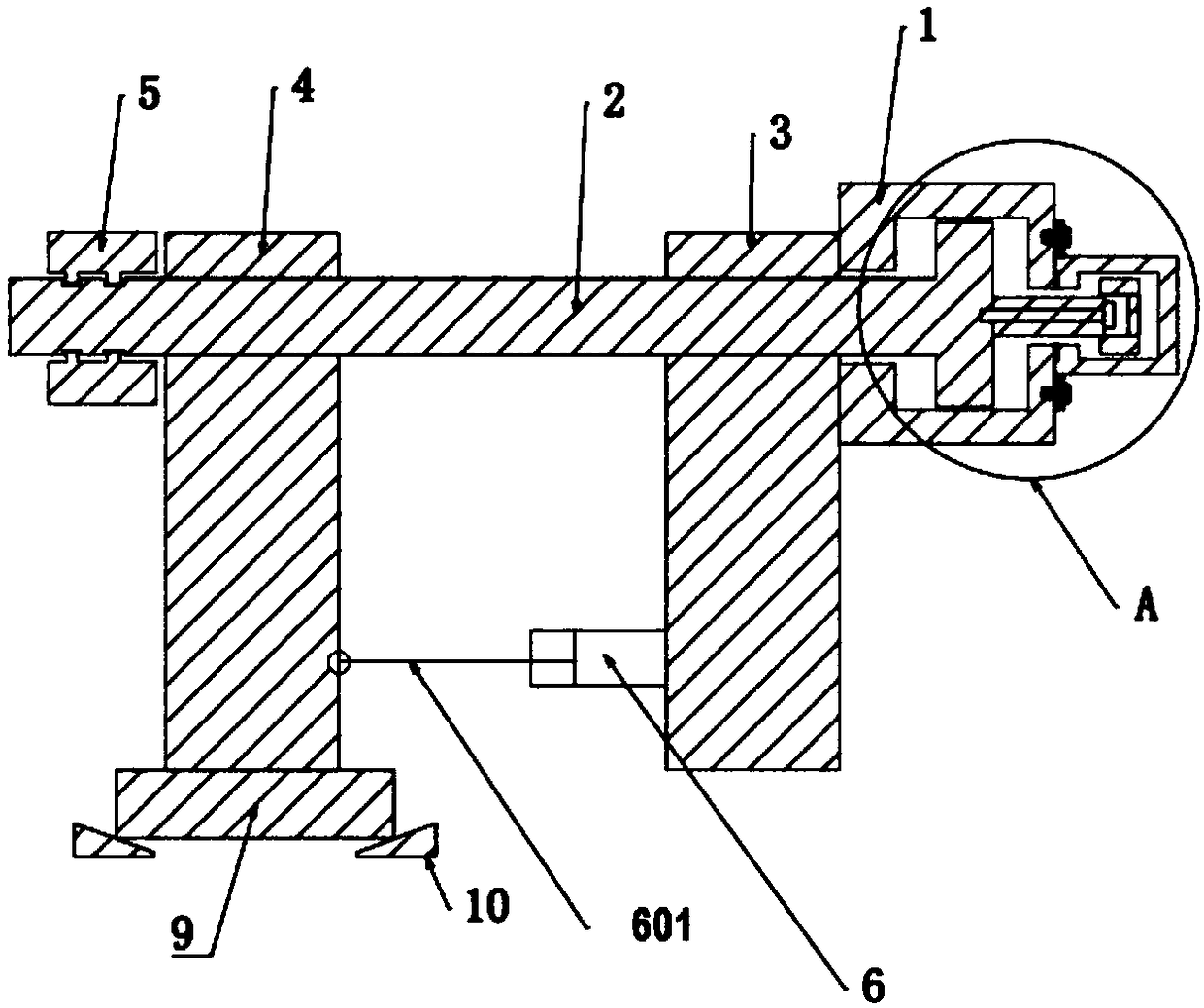
[0031] The clamping mechanism of the two-platen injection molding machine of prior art is as figure 1 As shown, it generally includes a fixed template 3, a movable template 4, a clamping cylinder 1, a pull rod, half lock nuts 5, a mold transfer cylinder 6, a supporting sliding foot 9, and an adjustment slant iron 10. The fixed template 3 and the movable template 4 are arranged in parallel at intervals, the mold-moving cylinder 6 is fixed on the fixed template 3, the mold-moving cylinder 6 is provided with a mold-moving piston rod 601, and the end of the mold-moving piston rod 601 is connected with the movable template 4 to realize For mold clamping and mold opening operations, the clamping cylinder 1 is set at the end of the fixed platen 3 away from the movable platen 4, the end of the clamping piston rod 2 far away from the fixed platen 3 is connected with a tie rod, and the pull rod and piston rod pass through the fixed platen 3 and the movable platen in turn. The template 4...


PUM


Abstract

The invention discloses a mold clamping mechanism of a two-plate injection molding machine. The clamping mechanism comprises a movable mold plate and a fixed mold plate that are arranged in parallel and at an interval, wherein a mold locking oil cylinder is arranged on one side, far away from the movable mold plate, of the fixed mold plate; the end part of a mold locking piston rod penetrates through the fixed mold plate and then is connected with the movable mold plate; a mold moving mechanism used for driving the movable mold plate to move along the mold locking piston rod is arranged between the movable mold plate and the fixed mold plate; a half-and-half brake nut capable of locking or unlocking the mold locking piston rod is arranged on one side, far away from the fixed mold plate, ofthe movable mold plate; a fine adjustment oil cylinder is fixedly arranged at one end, far away from the fixed mold plate, of the mold locking oil cylinder; the area of the cross section of the fineadjustment oil cylinder is smaller than that of the mold locking oil cylinder; a fine adjustment piston rod is arranged in the fine adjustment oil cylinder; the end part of the fine adjustment pistonrod is fixedly connected with a mold locking piston. The mold clamping mechanism of the two-plate injection molding machine has the advantages of being high in linkage degree, production efficiency and product quality.

Description

technical field [0001] The invention relates to the field of injection molding machines, more specifically, it relates to a mold clamping mechanism of a two-platen injection molding machine. Background technique [0002] With the development of the plastics industry, the requirements for plastic products are getting higher and higher, and the traditional toggle-joint injection molding machines have been difficult to meet the demand. The two-platen injection molding machine is widely used because of its simple structure and low cost. The mold clamping mechanism of the existing large-scale two-platen injection molding machine is shown in the figure. It generally includes a fixed platen, a movable platen, a mold clamping cylinder, a mold clamping piston rod, a half lock nut, and a mold transfer cylinder. On the template, the end of the piston rod is provided with a mold-moving piston rod, the other end of the mold-moving piston rod is connected with the movable template, the c...

Claims


Application Information

Patent Timeline
Patent Type & Authority Applications(China)
IPC IPC(8): B29C45/67
CPCB29C45/67
Inventor 周飞阮剑波王凯林吴俊胡绘国陈星欣
Owner HAITIAN PLASTICS MACHINERY GRP
Why Eureka
Try Eureka