
Outdoor split combined tire for electric locomotive

A technology for combining tires and electric locomotives, applied to road vehicle tires, motor vehicles, road vehicles, etc., can solve problems such as tire leaks, bulges, cracks or missing blocks, personal safety damage to drivers and passengers, and impact on safe driving. Achieve the effect of avoiding personal injury, reducing the risk of vehicle loss of control, and quick and convenient replacement

Active Publication Date: 2019-03-01
国网河南省电力公司伊川县供电公司 +1
View PDF9 Cites 0 Cited by
  • Summary
  • Abstract
  • Description
  • Claims
  • Application Information

AI Technical Summary

Problems solved by technology

[0002] As we all know, outdoor work is frequent in electric work, and the conditions of outdoor roads are very complicated, while electric locomotives are the most basic means of transportation, and tires on electric locomotives are one of the most important components on vehicles. Vehicles When driving on a variety of road surfaces, the tires are in direct contact with the road surface, and together with the vehicle's shock absorption system to relieve the impact of the vehicle while driving, once the tires are squeezed or pierced by external sharp objects during driving, It will cause air leaks, bulges, cracks or missing blocks of the tires, which will affect the normal and safe driving of the vehicle. Small damages on the tires also need to be replaced, causing unnecessary economic losses. In severe cases, it will cause damage to the vehicle. Out of control, causing traffic accidents, and also causing damage to the personal safety of drivers and passengers

Method used

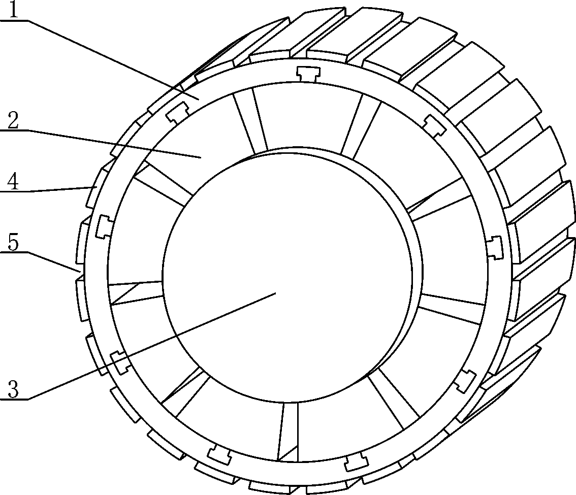
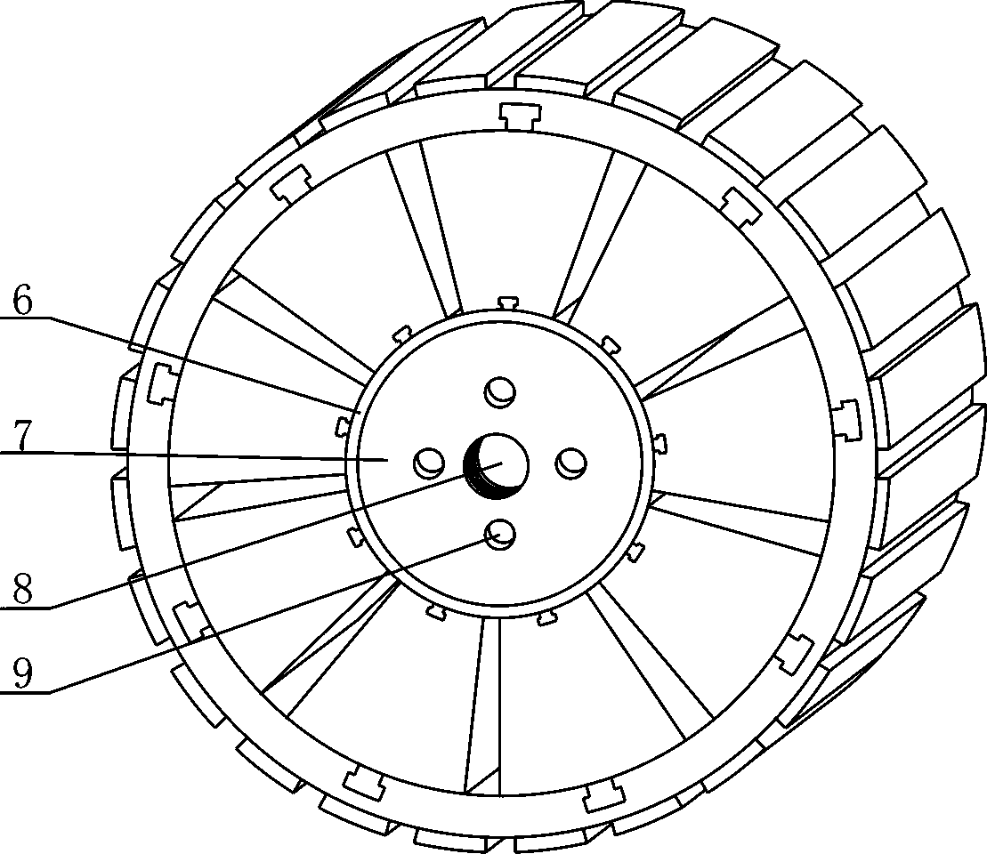
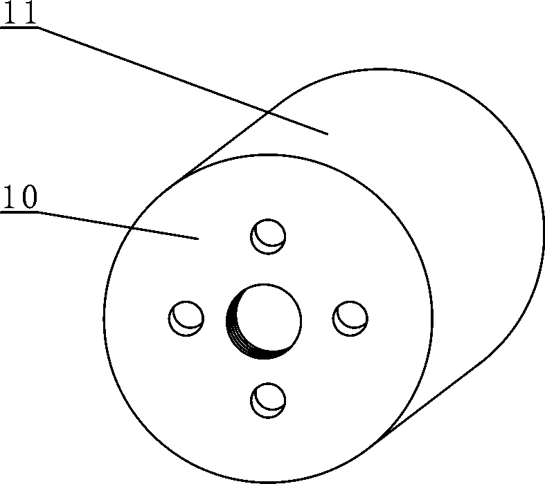

Image

  • Outdoor split combined tire for electric locomotive
  • Outdoor split combined tire for electric locomotive
  • Outdoor split combined tire for electric locomotive

Examples


Embodiment Construction

[0026] The present invention can be explained in detail through the following examples, and the purpose of disclosing the present invention is to protect all technical improvements within the scope of the present invention.

[0027] combined with Figure 1~8 An outdoor split-type combined tire for an electric locomotive, comprising an outer connecting pipe, a fixing block 17, a connecting block 16, an airbag 2, an inner connecting pipe, a sleeve 7 and a fixing device, the outer connecting pipe is provided with a fixing block 17, and the fixing block 17 is provided with connection block 16, and connection block 16 is provided with air bag 2, and air bag 2 is provided with inner connecting pipe, and inner connecting pipe is provided with sleeve 7, and sleeve 7 is provided with fixing device, and outer connecting pipe is provided with by the first A connecting pipe 1 and an anti-slip block 4 are formed. The first connecting pipe 1 is provided with an anti-slip block 4. The air ba...


PUM


Abstract

The invention relates to an outdoor split combined tire for an electric locomotive, and relates to the technical field of electric locomotive auxiliary equipment. A fixing block is arranged on an outer connecting tube, a connecting block is arranged on the fixing block, an air bag is arranged on the connecting block, an inner connecting tube is arranged on the air bag, a sleeve is arranged on theinner connecting tube, a fixing device is arranged on the sleeve, the external connecting tube consists of a first connecting tube and an anti-sliding block, the anti-sliding block is arranged on thefirst connecting tube, the air bag consists of an upper plate, an inflating cavity, a lower plate, an air tube and an air nozzle, the upper plate is provided with the inflating cavity, the inflating cavity is provided with the lower plate and the air tube, the air tube is provided with the air nozzle, the inner connecting tube consists of a second connecting tube, a sliding block and a limiting block, the second connecting tube is provided with the sliding block, the sliding block is provided with the limiting block, the sleeve consists of a bottom plate and a barrel body, the bottom plate isprovided with the barrel body, the fixing device consists of a fixing plate and a fixing shaft, and the fixing plate is provided with the fixing shaft. The outdoor split combined tire for the electriclocomotive is high in practicality and quite convenient to use, the risk that the locomotive is out of control due to damage of a tire in a running process is reduced.

Description

technical field [0001] The invention relates to the field of auxiliary technology for electric locomotives, in particular to an outdoor split type combined tire for electric locomotives. Background technique [0002] As we all know, outdoor work is frequent in electric work, and the conditions of outdoor roads are very complicated, while electric locomotives are the most basic means of transportation, and tires on electric locomotives are one of the most important components on vehicles. Vehicles When driving on a variety of road surfaces, the tires are in direct contact with the road surface, and together with the vehicle's shock absorption system to relieve the impact of the vehicle while driving, once the tires are squeezed or pierced by external sharp objects during driving, It will cause air leaks, bulges, cracks or missing blocks of the tires, which will affect the normal and safe driving of the vehicle. Small damages on the tires also need to be replaced, causing unne...

Claims


Application Information

Patent Timeline
Patent Type & Authority Applications(China)
IPC IPC(8): B60C5/20
CPCB60C5/20B60C2200/04Y02T30/00
Inventor 王倩韩洋于晓静许岩歌代高杰常成林方辉李霖
Owner 国网河南省电力公司伊川县供电公司
Learn More