
Elastomer internal flow circling structure constant pressure centrifugal pump

A technology of constant pressure and elastic body, which is applied in the field of pump body and constant pressure centrifugal pump with internal flow swirling structure, can solve the problems of unstable delivery pressure of centrifugal pumps, failure to meet the requirements of ceramic powder delivery, wear of metal impellers, etc., to achieve The effect of improving water conservancy efficiency, high water conservancy efficiency, and stable delivery pressure

Pending Publication Date: 2019-03-01
AIDI MACHINE HANGZHOU
View PDF0 Cites 2 Cited by
  • Summary
  • Abstract
  • Description
  • Claims
  • Application Information

AI Technical Summary

Problems solved by technology

[0002] In the process of conveying ceramic powder, not only a certain conveying pressure is required, but also the friction of ceramic powder is very large. If a volumetric pump such as a plunger pump is used for conveying, the steel sleeve is severely worn and has serious defects. Centrifugal pump conveying The pressure is unstable and cannot meet the requirements of ceramic powder transportation, and the wear of the metal impeller is also very serious. In view of this problem, it is necessary to design a pressure centrifugal pump with a constant internal flow of the elastic structure to solve the above problems.

Method used


Image

  • Elastomer internal flow circling structure constant pressure centrifugal pump
  • Elastomer internal flow circling structure constant pressure centrifugal pump
  • Elastomer internal flow circling structure constant pressure centrifugal pump

Examples


Embodiment Construction

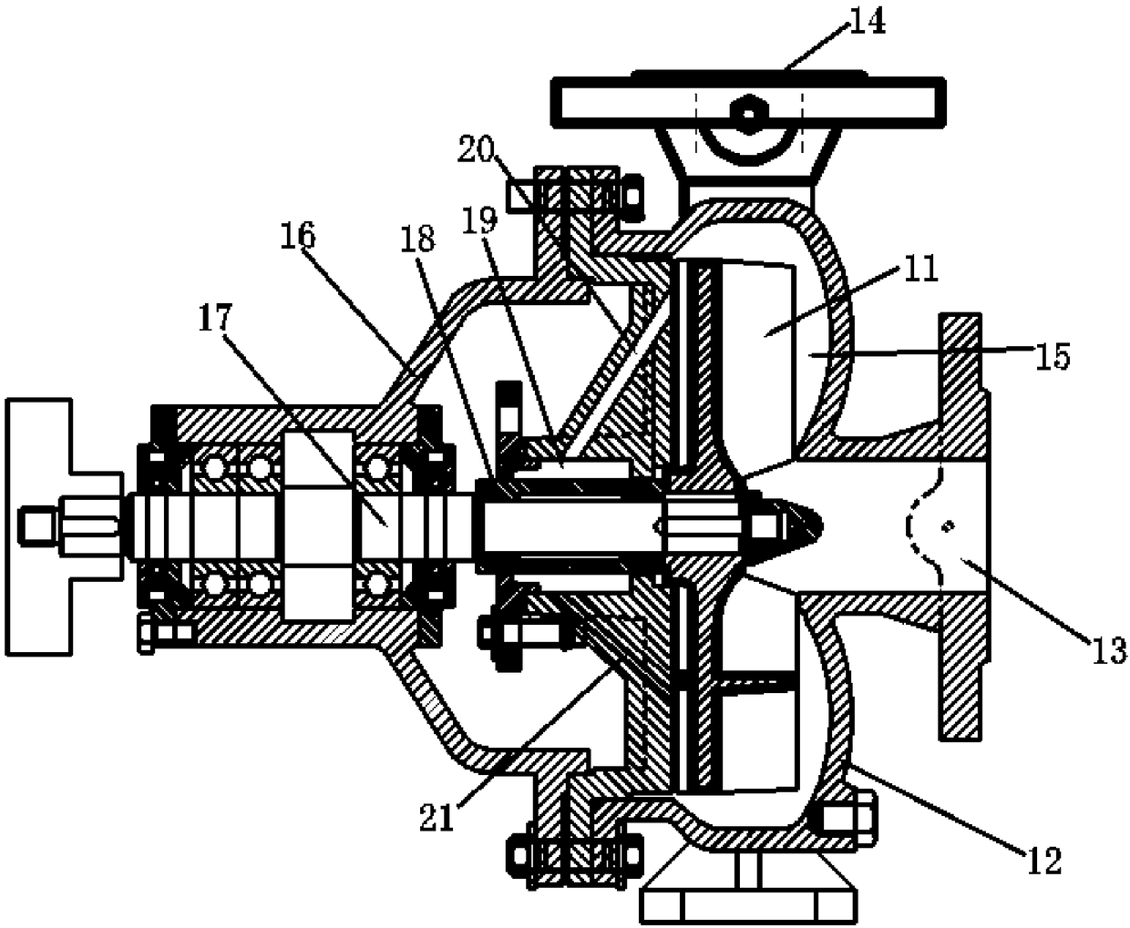
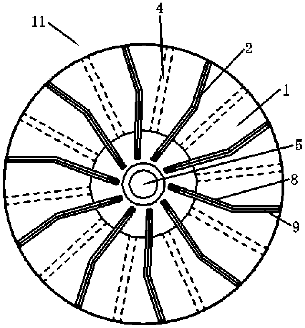
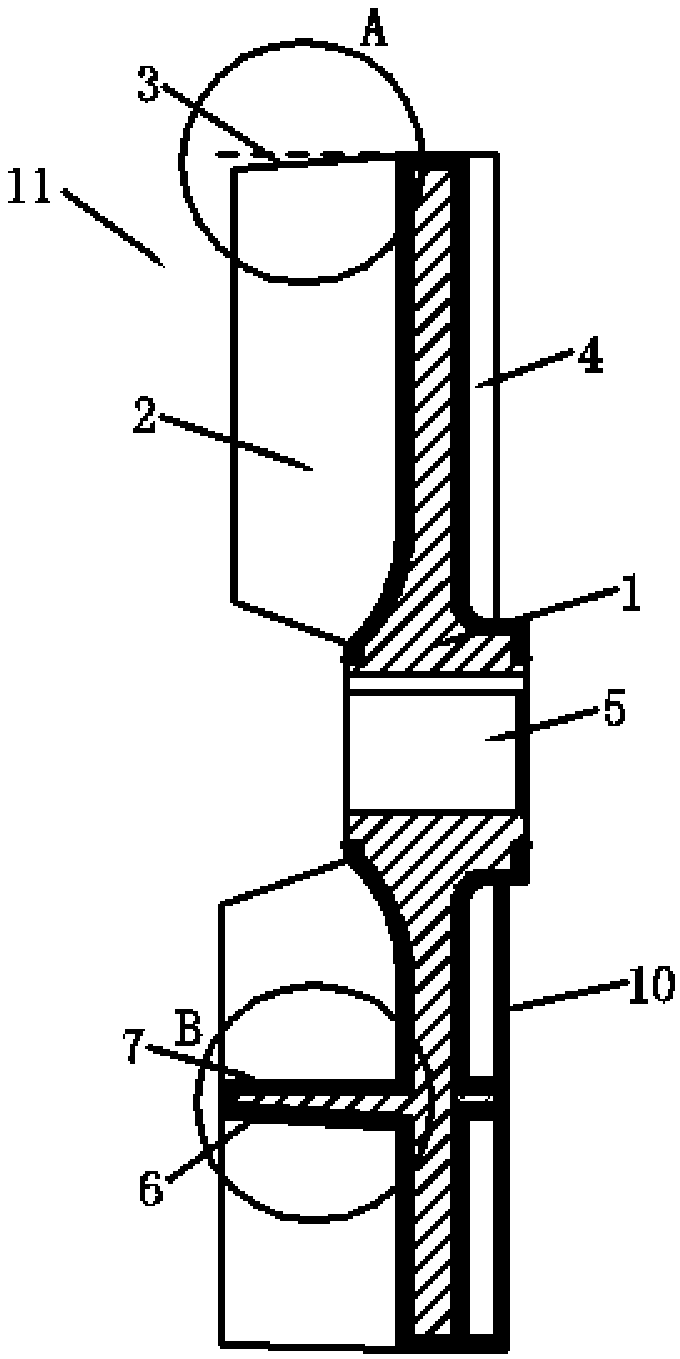
[0018] refer to Figure 1-Figure 6 , the present invention is a constant pressure centrifugal pump with an elastic internal flow swirling structure, including a main body 1, a main vane 2, an auxiliary vane 4, a rubber body 10, a front housing 12 and a rear housing 16, and one side of the main body 1 is provided with several main pumps. Blades 2, the other side of the main body 1 is provided with several auxiliary blades 4, the main blade 2 is formed by connecting the first straight blade 8 and the second straight blade 9, the first straight blade 8 and the second straight blade 9 form a Angle α, the angle range of α is 25°-35°, the ratio of the length of the first straight blade 8 to the length of the second straight blade 9 is 0.68-1, the outer edge 3 of the second straight blade 9 is a sloped side wall, the main body 1. The outer edge is a straight side wall. The angle between the edge of the second straight blade 9 and the outer edge of the main body 1 is β, which is 1.5°-...


PUM

PropertyMeasurementUnit
Thicknessaaaaaaaaaa

Abstract

The invention discloses an elastomer internal flow circling structure constant pressure centrifugal pump. The elastomer internal flow circling structure constant pressure centrifugal pump comprises amain body, main blades, auxiliary blades, a rubber body, a front shell and a rear shell; the main blades are arranged on one side of the main body, the multiple auxiliary blades are arranged on the other side of the main body, the main blades are formed through connecting of first straight blades and second straight blades, the front side faces of the first straight blades and the second straightblades are inclined side wall faces, and rear side faces of the first straight blades and the second straight blades are straight wall faces; a projection area of two adjacent main blades on the mainbody is divided into two parts with the equal area through the projection of the auxiliary blades on the main body, the rubber body is evenly arranged on the outer side wall of a rotating impeller, the rotating impeller is arranged in a conveying cavity of the front shell, a transmission shaft is rotatably arranged in the rear shell, a shaft sleeve is arranged in the rear shell, the shaft sleeve is arranged on the transmission shaft in a penetrating manner, and an upper cleaning way and a lower cleaning way are arranged in the rear shell. The pump is simple in structure, high in hydraulic engineering efficiency, stable in conveying pressure and capable of being widely applied and popularized.

Description

【Technical field】 [0001] The invention relates to the technical field of a pump body, in particular to the technical field of a constant-pressure centrifugal pump with an internal flow swirl structure. 【Background technique】 [0002] In the process of conveying ceramic powder, not only a certain conveying pressure is required, but also the friction of ceramic powder is very large. If a volumetric pump such as a plunger pump is used for conveying, the steel sleeve is severely worn and has serious defects. Centrifugal pump conveying The pressure is unstable and cannot meet the transmission requirements of ceramic powder, and the wear of the metal impeller is also very serious. In view of this problem, it is necessary to design a pressure centrifugal pump with a constant internal flow of the elastic structure to solve the above problems. 【Content of invention】 [0003] The purpose of the present invention is to solve the problems in the prior art, and propose a constant-press...

Claims


Application Information

Patent Timeline
IPC IPC(8): B65G53/46B65G29/00
CPCB65G29/00B65G53/4608
Inventor 连加俤孙富强朱佳佳聂静赵煜文
Owner AIDI MACHINE HANGZHOU
Learn More