Method for manufacturing closed impeller

a manufacturing method and closed technology, applied in the direction of wind motor components, non-positive displacement fluid engines, liquid fuel engine components, etc., can solve the problems of impeller itself not providing any means of inhibiting displacement, the relative displacement of the two members cannot be pressed together by a large force, and the impeller itself cannot provide any means of preventing displacement, etc., to achieve accurate fused center, easy to fuse, and simple

Active Publication Date: 2014-08-05
YAMADA MANUFACTURING CO LTD
View PDF11 Cites 10 Cited by
  • Summary
  • Abstract
  • Description
  • Claims
  • Application Information

AI Technical Summary

Benefits of technology

[0023]As described hereinabove, methods for increasing the efficiency of impellers, which are as important as flow paths for increasing the efficiency of water pumps, have been developed and implemented. Furthermore, in recent years a demand for low-cost vehicles has greatly increased. With the foregoing in view, the present invention provides a means for attaining increased efficiency at a low cost. The problem (technical problem or object) to be resolved by the present invention is to attain the increase in efficiency by improving an impeller, which is as important as flow paths, and realize the desired cost reduction.
[0027]Because of the “alignment action”, the displacement of the impeller blade and front plate in the radial (transverse) direction, which is the problem inherent to the related art, is eliminated. Therefore, after the front plate has been guided to the impeller blade tip surface and set thereon in the manufacturing process, subsequent fusion can result in fusing the front plate in the central position of the impeller by the alignment action of the impeller blade tip surface serving as a conical surface and the front plate serving as a conical surface. As a result, production quality and productivity can be greatly increased. As for the functions, because the front plate is fused without being shifted from the center, the center of gravity thereof is not displaced and rotational vibrations caused by non-uniform centrifugal force does not occur. The resultant merit is that the service life of the bearing is extended.
[0028]Further, because the front plate almost entirely covers the impeller blade, the desired discharge performance can be obtained. The resin melts at the sharp-pointed ridge-like protrusion and the impeller blade tip surface is practically not melted. Therefore, the front plate is fixedly attached to the impeller blade tip surface in an accurate contact position. Thus, the fusion position of the front plate can be accurately determined. With the above-described vibration generating means using (1) ultrasonic waves, (2) vibrations, and (5) high frequency, it is possible to produce the alignment action, which is the effect of the present invention, and fuse the front plate and the impeller blade together. Furthermore, describing the effect of the present invention in a simple manner, the alignment action makes it possible to conduct fusion in an accurate position, without providing the front plate with a groove for positioning. Thus, because no groove is present in the front plate, the front plate can be assembled in a simple manner, without confirming visually the attachment angle of the front plate. Therefore, production efficiency can be greatly increased.
[0029]According to the invention as in claim 2, efficient fusion is attained by forming the sharp-pointed ridge-like protrusion of almost uniform height and bringing the inner surface of the front plate into uniform contact with the sharp-pointed ridge-like protrusion. According to the invention as in claim 3, the shape is simple and cost can be reduced. According to the invention as in claim 4, there is a degree of freedom in selecting the shape and the discharge capacity can be further increased. According to the invention as in claim 5, fusion can be improved and production control can be facilitated by forming the front plate of the same material as the unit impeller blade plate. According to the invention as in claim 6, the alignment action can be easily produced even when the front plate is formed from a resin different from that of the unit impeller blade plate or from a different metal. Further, where the front plate is made from a metal, the thickness can be reduced by comparison with that obtained with the resin, while ensuring the same strength. Therefore, the height of the impeller blade can be accordingly increased and the discharge capacity can be further increased.

Problems solved by technology

Environmental concerns and cost efficiency issues created increased expectations and demand for vehicles with reduced fuel consumption.
Because the two members are made from a resin and the resin does not withstand a large force if the members are pressed against each other too strongly, the members cannot be pressed together by a large force.
Therefore, the aforementioned small vibrations cause relative displacement of the two members.
In this case, because the surfaces to be fused are flat, as described in Japanese Patent Application Laid-Open No. 53-54301, the impeller itself does not provide any means for inhibiting the displacement, and the two members move independently in the respective directions.
The resultant significant drawback is that the back surface shroud 3 and impeller blade portion 2 easily shift relative to each other in the radial (transverse) direction.
With the above-described fusion method, fusion can be attained, but although the fusion is possible, the following problems are encountered at the stage of actual implementation.
One means for reducing the displacement of the front plate and impeller in the radial (transverse) direction during fusion involves reducing the clearance between the front plate and the positioning member, but where the clearance is simply reduced, it becomes difficult to insert the front plate into the positioning member when the two are assembled.
The resultant problem is that productivity drops.

Method used


Image

  • Method for manufacturing closed impeller
  • Method for manufacturing closed impeller
  • Method for manufacturing closed impeller

Examples


Embodiment Construction

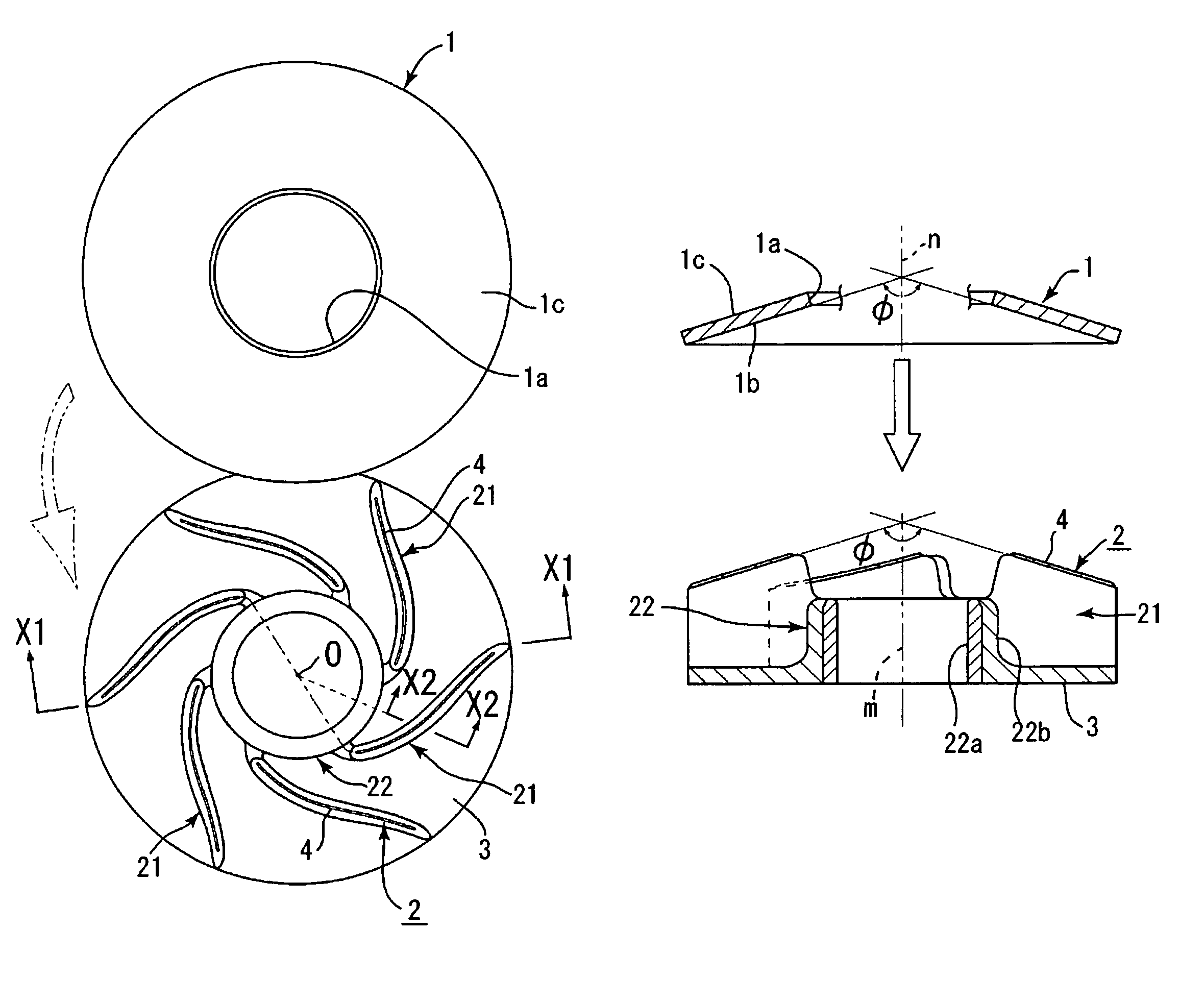
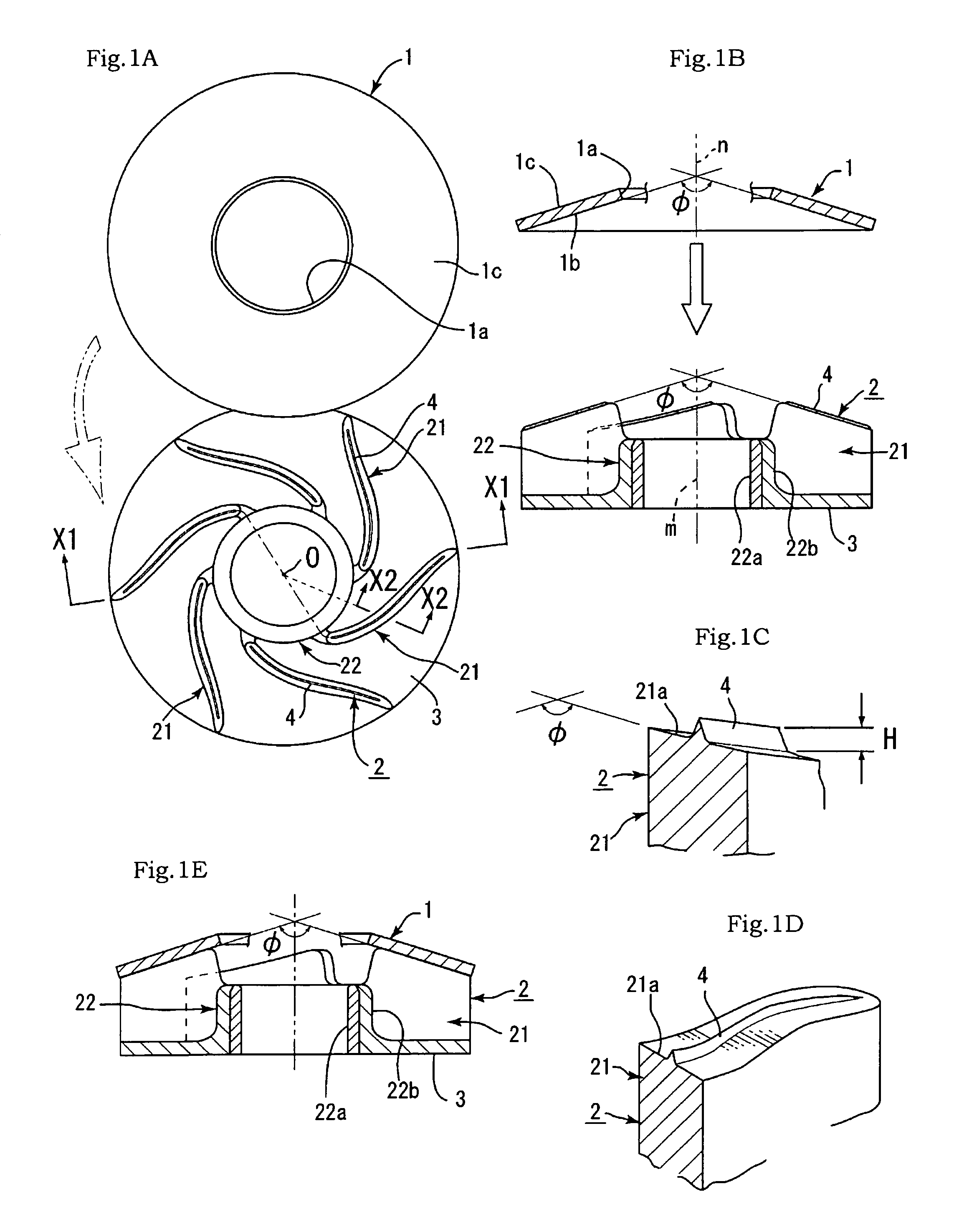
[0039]Embodiments of the present invention will be described below with reference to FIGS. 1 to 6. In the figures, the reference numeral 1 stands for a front plate that is an annular plate of a frustum shape (horn shape). In the cross-sectional view, the front plate is a disk (ring) having an open round hole 1a in the center and forming a convexity that narrows upward with respect to a vertical central axis n and has a height that decreases towards the outer periphery. The thickness of the front plate is about 1 to 2 mm and the material thereof is a synthetic resin. In the first embodiment, the front plate 1 is an annular plate of a flat horn shape obtained by cutting off the head section of any cone. In other words, in the first embodiment, a cone-shaped type is explained. The cone apex angle (also called “steric angle”) in the virtual apex location of an inner surface 1b (lower side in FIG. 1B) of the cone surface of the front plate 1 is denoted by φ (see FIG. 1B).

[0040]The refere...


PUM

PropertyMeasurementUnit
thicknessaaaaaaaaaa
projection heightaaaaaaaaaa
widthaaaaaaaaaa

Abstract

The present invention provides a method for manufacturing a closed impeller that has a simple configuration and enables fusion in a very accurate position. The method includes: forming a frustum-shaped front plate and a disk-shaped base plate formed therebelow, upper surfaces of a plurality of unit impeller blade plates made from a synthetic resin extending in radial directions which are formed as impeller blade tip surfaces, with sharp-pointed ridge-like protrusions having an acute upper end and a width less than a width of the impeller blade tip surface being integrally formed on the impeller blade tip surfaces. In the method, an inner surface of the front plate and the plurality of impeller blade tip surfaces are formed as parts of conical surfaces and formed so that the cone apex angles of the two conical surfaces are equal to each other. Then, the front plate is placed on the impeller blade and the ends of the sharp-pointed ridge-like protrusions and the inner surface of the front plate are brought into contact with each other. Small vibrations are then provided while applying an appropriate pressurizing force between the front plate and the impeller blade having the base plate attached thereto, the sharp-pointed ridge-like protrusions are melted, and the front plate is fused to the tip surfaces of the impeller blade.

Description

BACKGROUND OF THE INVENTION[0001]1. Field of the Invention[0002]The present invention relates to a method for manufacturing a closed impeller that has a simple configuration and enables fusion in a very accurate position.[0003]2. Description of the Related Art[0004]Environmental concerns and cost efficiency issues created increased expectations and demand for vehicles with reduced fuel consumption. A variety of means have been used to reduce fuel consumption, and increase in efficiency is one of them. Water pumps are provided on vehicles (vehicles equipped with a gasoline engine, hybrid vehicles, and electric automobiles) to cool the engine and warm up the cabin. Due to a recently created demand for reduced power consumption and therefore for increased efficiency, water pumps have also been the object of active development aimed at additional increase in efficiency.[0005]There are impellers for water pumps that are provided with the so-called front plate. Examples of such impellers ...

Claims


Application Information

Patent Timeline
Patent Type & Authority Patents(United States)
IPC IPC(8): B23P15/02
CPCF04D29/026B29C65/08B29C66/112B29C66/114B29C66/301B29C66/30223B29C66/322B29C66/5344B29C66/5346B29C66/54B29C66/8322B29L2031/7504F04D29/2227B29L2031/7496B29C66/116B29C66/12441F05D2300/43Y10T29/49316Y10T29/49Y10T29/49336F05D2230/232F05D2230/23
Inventor ADACHI, RYOUHEIFEI, SONGONO, HISAYOSHI
Owner YAMADA MANUFACTURING CO LTD
Why Eureka
Try Eureka