Compressor and air conditioning unit

A technology of compressors and components, applied in the direction of machines/engines, mechanical equipment, liquid fuel engines, etc., can solve problems such as air pressure leakage

Pending Publication Date: 2020-04-14
GREE ELECTRIC APPLIANCES INC
View PDF0 Cites 0 Cited by
  • Summary
  • Abstract
  • Description
  • Claims
  • Application Information

AI Technical Summary

Problems solved by technology

[0005] The embodiment of the present invention provides a compressor and an air-conditioning unit to solve the technical problem of air pressure leakage at the exhaust port of the impeller of the compressor in the prior art

Method used


Image

  • Compressor and air conditioning unit

Examples


Embodiment Construction

[0019] In order to make the object, technical solution and advantages of the present invention clearer, the present invention will be described in further detail below in conjunction with the embodiments and accompanying drawings. Here, the exemplary embodiments and descriptions of the present invention are used to explain the present invention, but not to limit the present invention.

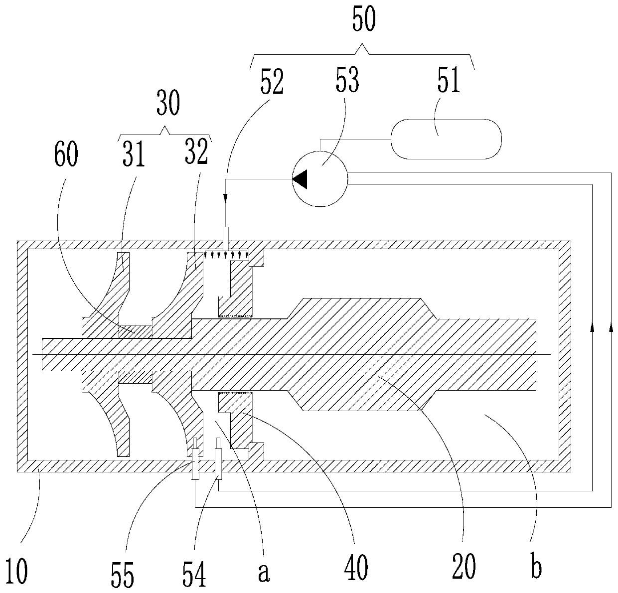
[0020] In view of the deficiencies in the prior art of reducing leakage through comb-tooth seals alone to balance the pressure on both sides, a high-energy-efficiency compressor aerodynamic structure that can be adjusted is designed, so that the pressure in the area behind the impeller 30 is the same as that in the aerodynamic flow channel. The exhaust pressure at the outlet of the impeller 30 is equivalent, so that the pressure leakage loss in the aerodynamic flow channel can be controlled within the minimum range, thereby further improving the efficiency of the impeller 30 of the centrifugal c...


PUM


Abstract

The invention provides a compressor and an air conditioning unit. The compressor comprises a compressor base body, a motor shaft, an impeller and a sealing piece, the motor shaft is rotatably installed in the compressor base body, the impeller is installed on the motor shaft, and the sealing piece is installed on the motor shaft. A first cavity is formed between the front face of the sealing pieceand the back face of the impeller, and a second cavity is formed between the back face of the sealing piece and the compressor base body. A pressurizing assembly is connected with the first cavity and used for supplying a refrigerant into the first cavity so as to keep the pressure of the first cavity to be equal to the pressure of an exhaust port of the impeller. By applying the technical scheme, the pressure leakage loss of the exhaust port of the impeller in a pneumatic flow channel is controlled within the minimum range, so that the impeller efficiency of the compressor is improved, the performance of the compressor is also improved, and the operation energy efficiency of the air conditioning unit is improved.

Description

technical field [0001] The invention relates to the technical field of refrigeration equipment, in particular to a compressor and an air conditioner unit. Background technique [0002] In centrifugal compressors, the most direct impact on the energy efficiency of the unit is the work efficiency of the impeller. The higher the efficiency of the impeller, the higher the energy efficiency of the unit. The efficiency of the impeller depends on the structure of the impeller itself and the leakage in the aerodynamic channel of the compressor. When the impeller structure has been finalized, the work efficiency of the compressor impeller is further improved by reducing the leakage in the aerodynamic channel, thereby further improving the centrifugal unit. energy efficiency. [0003] Generally speaking, on both sides of the comb seal, there is a certain difference between the pressure behind the impeller of the centrifugal compressor and the pressure in the bearing lubrication or co...

Claims


Application Information

Patent Timeline
Patent Type & Authority Applications(China)
IPC IPC(8): F04D25/06F04D17/12F04D29/10F04D29/00F04D27/00
CPCF04D17/12F04D25/06F04D27/00F04D27/001F04D29/002F04D29/102
Inventor 刘华张治平李宏波钟瑞兴蒋楠
Owner GREE ELECTRIC APPLIANCES INC
Why Eureka
Try Eureka