Automatic concrete pouring device for building construction

A building construction and automatic pouring technology, applied in clay preparation devices, construction, unloading devices, etc., can solve the problems of uneven pouring, high working intensity, and increased concrete viscosity, saving labor costs, manufacturing and use. cost effect

Inactive Publication Date: 2020-03-24
菏泽城建工程发展集团有限公司
View PDF8 Cites 10 Cited by
  • Summary
  • Abstract
  • Description
  • Claims
  • Application Information

AI Technical Summary

Problems solved by technology

[0004] Although the above-mentioned patents have solved the problems of large amount of work, high work intensity, high labor cost, long construction period and low efficiency in the prior art of manual pouring of concrete, this solution still has the following disadvantages:
[0005] This solution is to pour the mixed concrete into the concrete pouring hopper for pouring. Although the effect of automatic concrete pouring can be achieved, but with the evaporation of water in the concrete during the pouring process, the concrete in the pouring hopper The viscosity will become larger and larger, so after a period of use, the pouring nozzle of the pouring bucket will be blocked by the concrete with increased viscosity, which will affect the continuous pouring, and the high viscosity of the concrete will cause greater resistance to the operation of the mixing mechanism, which will easily cause motor failure. The high-load operation of the concrete is not only a waste of electricity, but also easily causes damage to the motor, and this solution does not provide a solution to the problem of the increase in the viscosity of the concrete during the pouring process;
[0006] This solution does not take into account the quantitative pouring of concrete when pouring concrete, so the pouring volume of concrete cannot be controlled during pouring, and uneven pouring at various locations is prone to occur;
[0007] After the concrete is poured, this solution only installs a hot air device to dry the concrete, and does not install a troweling device to smooth and polish the poured concrete. Therefore, although the automatic pouring of the concrete can be realized, the concrete needs to be troweled manually , not only the labor cost is high, but also the speed of automatic concrete pouring is fast, and it is difficult for the staff to keep up with the smoothing work

Method used


Image

  • Automatic concrete pouring device for building construction
  • Automatic concrete pouring device for building construction
  • Automatic concrete pouring device for building construction

Examples


Embodiment 1

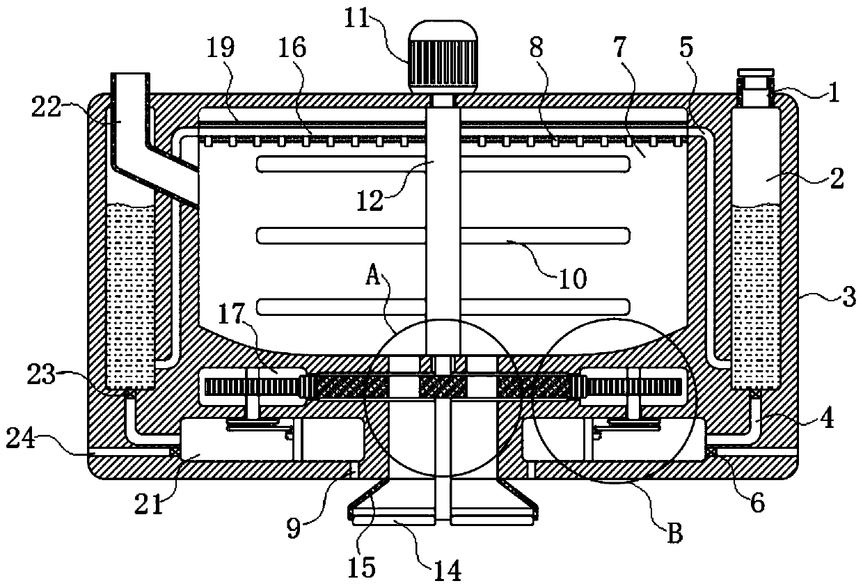
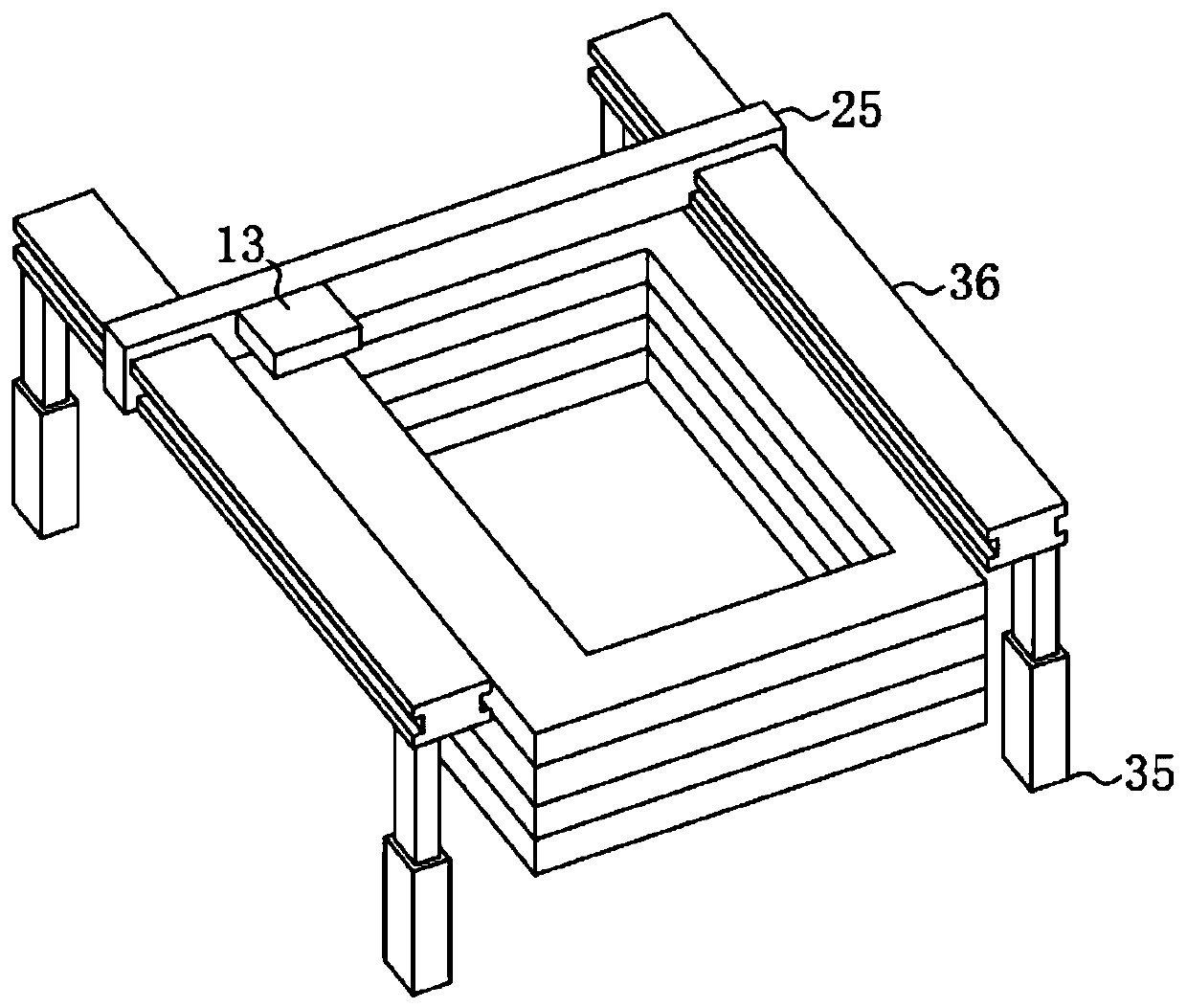
[0033] refer to Figure 1-6 , an automatic concrete pouring device for building construction, including two guide rails 36 fixed on the ground through two electric telescopic rods 35, a beam 25 sliding along the two guide rails 36, and a concrete pourer 13 slidingly connected to the beam 25 , a controller is installed on the guide rail 36, and a motion mechanism coupled with the controller is installed on the crossbeam 25 and the concrete pourer 13. The motion mechanism can be controlled by the controller to push the crossbeam 25 and the concrete pourer 13 to move. technology, so I won’t go into details here.

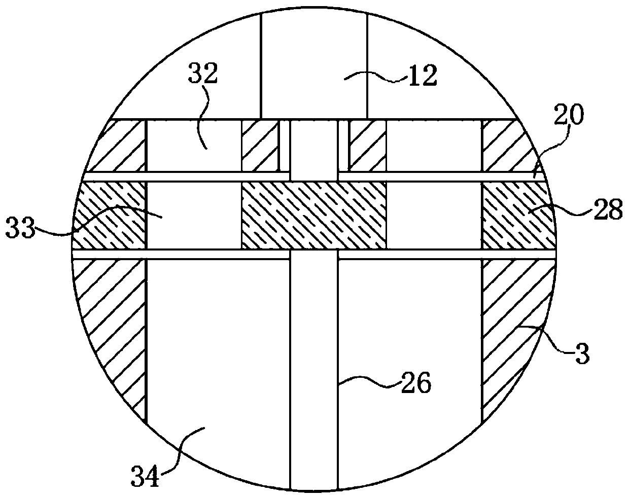
[0034]Concrete pourer 13 comprises pouring box 3, motor 11, stirring shaft 12 and a plurality of stirring blades 10, and motor 11 is fixedly connected on the upper end of pouring box 3, and stirring shaft 12 is fixedly connected on the end of motor 11 output shafts, and stirring shaft 12 Located in the pouring box 3, a plurality of stirring blades 10 are evenly distrib...

Embodiment 2

[0053] refer to Figure 7 , and embodiment 1 is different in that: ram board 31 changes vertical plate into L-shaped plate, air outlet 9 is changed into bar-shaped hole by circular hole, and the lower end of ram board 31 is fixedly connected with plasterboard 18, And the plasterboard 18 is slidably connected in the air outlet hole 9 .

[0054] It should be noted that, in order to ensure that the pouring nozzle 15 does not hinder the movement of the troweling board 18, the troweling board 18 is designed to be in the same shape as the side of the pouring nozzle 15. It is located at the center directly below the pouring nozzle 15, and two plasterboards 18 are attached to each other in this state.

[0055] The horizontal reciprocating movement of the ram board 31 can simultaneously drive two plastering boards 18 to horizontally reciprocate slide in the air outlet 9, thereby smoothing the concrete spread by the spreading board 14, which not only saves a lot of labor costs, but als...


PUM


Abstract

The invention discloses an automatic concrete pouring device for building construction. The automatic concrete pouring device for building construction comprises two guide rails fixed to the ground through two electric telescopic rods respectively, a cross beam sliding along the two guide rails, and a concrete pouring unit slidingly connected to the cross beam. The concrete pouring unit comprisesa pouring box, a motor, a stirring shaft and a plurality of stirring blades, and the motor is fixedly connected to the upper end of the pouring box. According to the automatic concrete pouring devicefor building construction, by arranging a dilution mechanism, a quantification mechanism, a water pumping mechanism, a spreading mechanism and trowels, concrete in the concrete pouring unit can be stirred and diluted, the situation that the viscosity of the concrete is excessively increased due to water evaporation is avoided, and blockage of the concrete pouring unit and high-load operation of the motor are prevented; quantitative pouring of the concrete can be achieved, and it is guaranteed that the concrete is uniformly poured; and besides, the concrete can be automatically spread and troweled after being poured, and thus the problem that automatic concrete pouring is fast and it is difficult for workers to perform troweling synchronously is solved.

Description

technical field [0001] The invention relates to the technical field of building construction machinery and equipment, in particular to an automatic concrete pouring device for building construction. Background technique [0002] At present, concrete pouring or wall laying in building construction is realized manually, but manual operation has problems such as workload, high work intensity and high labor cost, and manual pouring concrete or wall laying has problems such as long construction period and low efficiency. [0003] In view of the above problems, the authorized patent document with the application number CN201310187282.6 discloses an automatic concrete pouring device for building construction, including a guide rail device and a crossbeam sliding along the guide rail device, the crossbeam is fixed with a steel bar insertion device and a concrete pouring bucket, A hot air blower device for drying concrete is also arranged beside the concrete pouring hopper. [0004]...

Claims


Application Information

Patent Timeline
Patent Type & Authority Applications(China)
IPC IPC(8): E04G21/04B28C5/16B28C7/12B28C7/16
CPCB28C5/16B28C7/126B28C7/16E04G21/04
Inventor 王美英
Owner 菏泽城建工程发展集团有限公司
Why Eureka
Try Eureka